Category Archives: Radio history

1940 Emerson Radios

EmersonAd011940

Seventy-five years ago, Gimbels Department Store in Milwaukee ran this ad for Emerson radios in the January 19, 1940 edition of the Milwaukee Journal.

For $9.95, you could get the standard broadcast receiver with a “miracle tone chamber” and built-in loop antenna. It came with a “safety power cord,” which apparently meant that it didn’t have a “curtain burner” cord with built-in dropping resistor for the filaments. This appears to be the Emerson Model 330 in a bakelite case.  You can see the radio in operation at this YouTube video.  Another nice example, along with the schematic, can be found at RadioMuseum.org or at N9DD’s site.

$19.95 would get you a six-tube set that tuned police calls as well as the 49-meter shortwave band. It appears to have two bands, meaning that the police calls were probably at the top end of the standard broadcast band.

And for $29.95, you could get the seven-tube set which also covered the broadcast and shortwave bands for “complete foreign and American Broadcasts” with “EXCELLENT tone.” This one appears to be similar to the Emerson Model 356, but with a slightly different cabinet. A nice video of a restored model in operation can be found at YouTube.

Click Here For Today’s Ripley’s Believe It Or Not Cartoon


Taking the Girls for a Spin on the Radio-Equipped Ice Yacht

IceYacht

Ninety years ago, DeWolf Barton discovered the secret of attracting the girls: Just offer them the chance to go out for a spin on the ice of Lake Placid aboard his ice yacht. Barton, shown to the left piloting the craft, is joined by Virginia Markel of Cambridge, Mass., Dorothy Knoepke of South Orange, N.J., Patricia Schmidt of New York City, and Eloise Thompson of New Haven.

The radio is said to be a superhetrodyne fed by a “concealed loop” for an antenna.  Mr. Barton was apparently a particularly skilled navigator of the craft, since there’s no mention of the boom of the sail knocking over the precariously placed speaker.  This photo appeared in the January 17, 1925, issue of Radio World.

VirginiaMarkelMiss Markel was apparently no stranger to winter sports. She is shown here skiing at Lake Placid, from the December 27, 1928, issue of the Niagara Falls Gazette.

Click Here For Today’s Ripley’s Believe It Or Not Cartoon


W9XJL: Duluth-Superior Shortwave Broadcast Station

W9XJL QSL card,

W9XJL 1938 QSL card, All Wave Radio, Feb. 1938.  A color image of the card can be found at this link.,

You probably didn’t know that Superior, Wisconsin, was once the home of a shortwave broadcast station. Station W9XJL was an experimental station licensed to Head of Lakes Broadcasting Company.  It originally operated with 80 watts on 26.10 MHz, and later increased its power to 250 watts. The January 1940 issue of Radio & Television magazine carries the following report:

W9XJL, 26.10 mc, Superior, Wis., is now using a full 250 watts from 9 a.m. to 5 p.m. daily. Much can be said for the fine quality and consistency this station has shown in the last three years and for its excellent verification policy. Our observers in Massachusetts, Connecticut, New Jersey, Florida, Arizona, California and Washington all report an R9 signal whenever the band opens.

w9xjl

WEBC-W9XJL advertisement, 1939 Broadcasting Yearbook.

W9XJL  simulcasted  Duluth-Superior station WEBC on the Apex band, which existed from 1934 to 1940. The 11 meter band (25-27 MHz) was allocated internationally for broadcasting, but largely unused outside of the U.S. Apex stations. In Minnesota, both WCCO and WTCN had licenses to broadcast on the Apex band, as W9XHW and W9XTC respectively.  (A portion of the band, 25.6-26.1 MHz, is still allocated for international broadcasting, but rarely used.)  Some sources incorrectly describe W9XJL as an FM station, but it actually used amplitude modulation, although the Apex stations generally used a wider bandwidth than on the standard broadcast band, thus allowing for a more “high fidelity” audio signal.

W9XJL transmitted from 40th and Tower Avenue in Superior.  The program was generally the same as WEBC, with an announcer at the transmitter location breaking in to give the station identification.  One interesting use of the station was reported in 1937 as the relay of personal messages to and from persons wintering on Isle Royale. Station WSHC was licensed to Isle Royale.

W9XJL did receive reception reports from around the world.  As noted above, it had a good reputation for QSL’ing.

References


Click Here For Today’s Ripley’s Believe It Or Not Cartoon


Civil War Veteran and the Radio

OldSoldierRadioThis photo from the October 14, 1922 issue of Radio World shows a veteran of the Civil War listening to the radio. According to the caption: “The Grand Army veteran . . . wanted to listen in and the owner of a set obliged him. Before he had satisfied his longing, the old soldier was able to tune in himself…. The old fighter said that becoming acquainted with this new wonder gave him a new lease on life.”

While there might be a few younger, most Civil War veterans at that time would have been at least 75 years old. (A man born in 1847 would have been 18 years old at the time of the war.) He was probably born in the Polk administration, fought in the Civil War, and his sons or even his grandsons could have fought in the Spanish-American War or the First World War. The telegraph was barely in existence when he was born, and he lived to see electrification, motor cars, phonographs, the telephone, and even radio.

The world became a very different place during this one lifetime.


Click Here For Today’s Ripley’s Believe It Or Not Cartoon


How To Tune a Regenerative Receiver

1925RadioNews

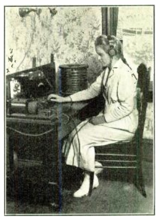
Ninety years ago, this young woman demonstrates the proper method for tuning a regenerative receiver. She is shown in the January 1925 issue of Radio News.  The caption explains that the control on the left is tuning, and the one on the right controls regeneration.

Click Here For Today’s Ripley’s Believe It Or Not Cartoon


1947 One Tube Regenerative Receiver from Popular Mechanics

PMJan47RadioFido is shown here assisting with the construction of this simple one-tube radio from the January 1947 issue of Popular Mechanics. The radio is a very simple regenerative receiver described as a “student set.” The tuning range is 550-1200 kHz, meaning that the top part of the AM broadcast band is cut off. The article notes that this limited tuning range was used “for simplicity and to enable the builder to find the component parts in current radio catalogs.” In particular, instead of having the builder wind the coil, the plans call for a standard oscillator coil intended for a superheterodyne receiver.

PMJan47Radio2The receiver uses a single 117N7 tube, which combines a pentode and rectifier in the same tube. Therefore, both the filaments and the B+ can be obtained from an AC line cord. The chassis is simply a wooden base supported by cabinet knobs. Most of the wiring is under the chassis, although the high voltages are easily accessible to anyone who picks up the radio when it’s plugged in, which probably wouldn’t fly today. The radio puts out enough audio to drive a 5″ speaker, which is simply mounted facing down.

As with many Popular Mechanics electronic projects, the set was also available in kit form from Allied Radio.  It could be found in the 1948 catalog for $10.50.

Most of the parts should be readily obtainable. The most difficult would be the coil, but it is available from Antique Electronic Supply.  It could also be scavenged from an old five-tube AM radio. The tube is available from TubeDepot.com.  For more ideas on where to find parts, you can visit my Crystal Set Parts page or Jameco Electronics.


Hoosier Girls Build Radio, 1922

DorotheaAliceHanna

Shown here are Dorothea and Alice Hanna of Indianapolis, Indiana, ages 13 and 15, along with the radio they constructed according to plans published in the April 22, 1922 edition of Literary Digest. The set was designed by 21-year-old James Leo McLaughlin of New York, shown below along with his radio.SimpleXtalSet

In a letter to the magazine, the girls’ father reported that they arrived home from school with the copy of the magazine, and immediately pooled their allowances and set off to purchase the required parts at an electric store and stationery store. They had the set assembled by 6 PM. The next afternoon, “refuing all help from father or brother” they had the aerial and ground installed. They were soon receiving programs, “when many expensive sets reported only fragments or no sounds at all.”

The father reported that the girls had never studied physics and had never seen or heard wireless. Their sole assistance was driving the ground pipe into the ground and securing the switch to the side of the house.

The father reported that the girls’ total expenditure was $6.30, which he concluded was well invested.


Click Here For Today’s Ripley’s Believe It Or Not Cartoon


1915 Radio Controlled Boat


Nautalia1915A hundred years ago, Popular Mechanics, January 1915, shows the Natalia, a radio controlled boat, and reports a test in which the unmanned vessel sailed from Boston Harbor 28 miles into open seas, controlled only by the wireless transmitter located as far as 20 miles from the boat.

As a backup, the boat could be controlled by light, since it was equipped with selenium cells which responded to light beams. While the details of this Army-Navy experminet were not revealed, it was believed that the receiver aboard the boat was equipped with a new type of coherer. The boat was equipped with a motor which actuated the boat’s steering wheel.

Click Here For Today’s Ripley’s Believe It Or Not Cartoon


1965 Emergency Crystal Set from Boys’ Life

BL1965XtalSet

In an earlier post, we looked at a one-transistor CONELRAD receiver featured in Boys’ Life magazine in 1956.  And today, we look at a simpler variation on the same theme, this time from 50 years ago this month, in Boys’ Life magazine January 1965.

Once again, the Scout’s obligation to Be Prepared is inspiration for this electronic construction article.  It’s a basic crystal set, but the focus is on being prepared, under the title EMERGENCY COMMUNICATIONS.

A terrified family, clad in pajamas, is apparently confronting rising flood waters. The text warns that “in an emergency, communication is important and communications preparedness should be a part of your ‘family alert’ plan.” It goes on to warn that if electric power is out, a crystal set may be the only way to keep in touch with latest news, disaster reports, and emergency instructions.

The page details how to build the radio using a galena detector with either a safety pin or piece of coiled wire. It acknowledges that a germanium diode can also be used but “isn’t as much fun” because it lacks the thrill of finding a sensitive spot on the crystal.

No author is listed, and the construction details are a bit lacking in detail. (In particular, no mention is made that the insulation has to be removed from the top of the coil in order to contact the slider.)

If you were a Scout 50 years ago, you were prepared. And a flood was nothing. You needed the additional thrill of finding the sweet spot on the crystal.

All of the parts for this set are readily obtainable.  If you’re having trouble finding any, you can find them on my crystal set parts page.


US Embassy in Tokyo After Pearl Harbor: The Secret Radio

US Embassy Tokyo, 1931 photo.  (US Gov't photo).

US Embassy Tokyo, 1931 photo. (US Gov’t photo).

The website of the Association for Diplomatic Studies and Training contains a very interesting account of life in the U.S. Embassy in Tokyo after Japan’s attack on Pearl Harbor.  It is the reminiscences of Robaert A. Fearey, who served as personal secretary to Joseph Grew, the U.S. Ambassador to Japan from 1932-41.

Fearey had recently graduated from college, and had a 4-F draft status due to eye problems.  He had been recommended by his college for the assignment, and sailed for Japan in early 1941.  On the morning of December 8, he, along with the rest of the embassy staff, heard of the attack on Pearl Harbor.  Late in the morning, a car from the Foreign Ministry arrived with the official notification.

The staff of the embassy was interned in the embassy compound until June, when they were repatriated on a well-lighted Japanese ship via Mozambique.  The journalists with whom they sailed home had been assumed to be spies and were tortured.  The embassy staff, however, was allowed to remain relatively unmolested on the embassy grounds.  The staff was even able to witness the Doolittle Raid of April 18, 1942.

One condition imposed by the Japanese was that the embassy was not allowed to retain any radio transmitter or receiver.  The embassy didn’t have any transmitter, instead relying on commercial telegraph.  The ambassador protested the seizure of radio receivers, but to little avail.  The Japanese searched the compound for radios and seized them.

But Fearey reports that he kept one radio:

Again demonstrating youthful indiscretion, I went back to my apartment and effectively hid a tiny pocket radio which a college housemate and amateur radio expert had made for me and which I had brought along to Japan. The radio was about five inches long, three inches wide and three-quarters of an inch thick and had what my friend had told me might be two of the smallest tubes ever made. I carried it inside the upper pocket of my jacket, with holes cut in the pocket so I could reach in to turn the control knobs. a thin wire ran
up under the back of my coat to a small, almost invisible ear plug. With this device, I had been able, unbeknownst to anyone, to listen to the radio during classes at college and even when riding my motorcycle. In Japan, I had tried it out a few times and had no
trouble receiving Japanese language stations. In our current predicament, I thought it might be a useful source of information, and in any case, I did not want to lose it. The searchers never found it, and it did prove to be a moderately useful source of information
until the tiny batteries wore out. I brought it back to the States on the repatriation ship.

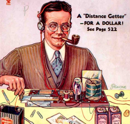
It seems likely that the radio in question was similar to the one shown here on the cover of the September 1935 issue of Radio Craft magazine.

SmallestRadio1935

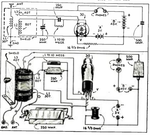
The description of Fearey’s clandestine radio seems to match up with the description of the 1935 project.  The 1935 receiver was one tube, and Fearey reports that his contained two tubes.  So chances are, the unnamed builder of Fearey’s set added an extra stage of amplification.  But it seems to be the same general design.

Fearey reports the size of his radio as being about 5 by 3 by 3/4 inch, with “two of the smallest tubes ever made.” The Radio Craft design doesn’t specify the dimensions, but reports that it was built in a bakelite cigarette case designed to hold ten cigarettes. The radio in the article uses an English tube which does appear to be the smallest in production at that time.

And significantly, the construction article notes that crystal earphones are used. While the article shows the set used with a pair of headphones, a crystal earphone was available at that time, as noted in the article. The article calls for 25-30 feet of wire for the antenna, but with a strong station and/or the additional tube, the use of the smaller antenna described by Fearey seems plausible.

The schematic and pictorial diagrams of the Radio Craft set appear below.

SmallestRadio1935Diagram

Fearey’s account is also available as a web page with additional illustrations.


Click Here For Today’s Ripley’s Believe It Or Not Cartoon