Monthly Archives: February 2022

Laco Kitcraft Model 200 One-Tube Radio, 1947

1947FebPS5LacoKitcraftSeventy-five years ago this month, the February 1947 issue of Popular Science showed this simple one-tube radio kit, the Laco Kitcraft Model 200.  The kit sold for $6, and featured a single 1L4 (or 1T4 or 1U4) tube, and required 1-1/2 volts for the filament, and anywhere from 22-1/2 to 90 volts for the B+.

According to the magazine, it was perfect for the youngster who wanted his or her own radio.


Anemometer With No Moving Parts

1957FebPE10If Junior wants to take home the blue ribbon at the next science fair, this project will almost certainly provide it. When Junior announces to the science teacher that he or she is going to build an anemometer (an instrument for measuring wind speed) with no moving parts, the teacher will be mystified, and will wonder whether it is even possible. But when they see the completed device in action, they will be astonished at its simplicity.

1957FebPE11
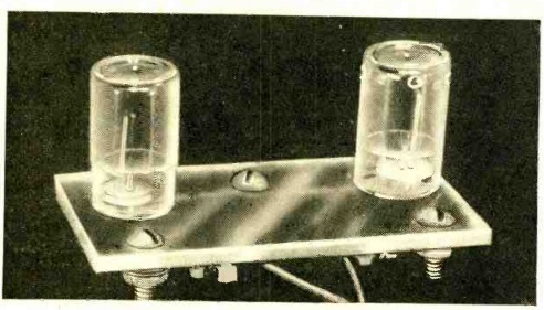
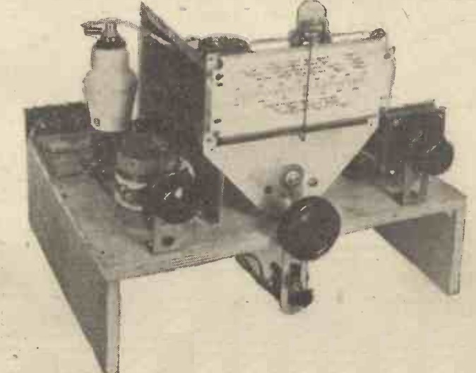
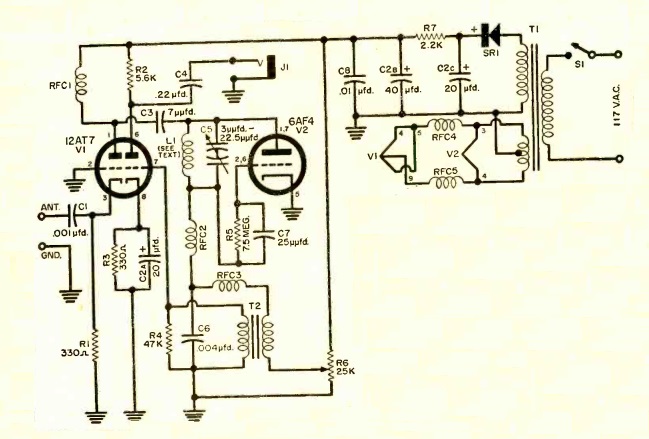
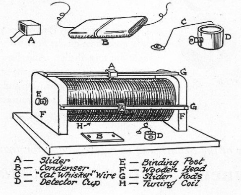
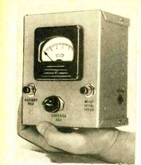
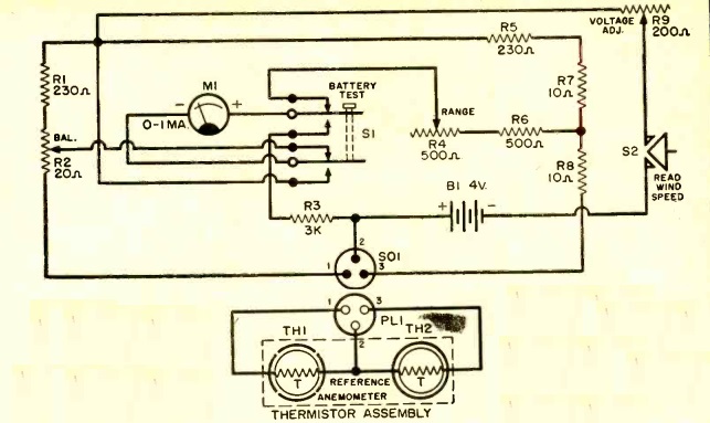
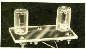
The anemometer consists of a Wheatstone bridge circuit, which consists of four resistors. Two of the resistors are actually thermistors of equal value. As long as their resistance remains equal, the meter shows a reading of zero. But if they are unequal, then the meter displays a current. The two thermistors are placed outside at the spot where the wind is to be measured. When they are energized, they heat up slightly, which causes their resistance to change. As shown at left, both are mounted in a small plastic container, but one of those containers has small holes drilled in it. When it is exposed to the wind, it is cooled, but the other thermistor is not. The stronger the wind, the greater the cooling, and the current increases. In other words, as the wind increases, it is shown on the meter.

Once the meter is built, it needs to be calibrated, and that requires Junior to “enlist the services of a competent automobile driver” on a “highway which permits maximum state speed limits.” The driver accelerates to 60 MPH, and Junior holds the thermistor assembly out the window, as far as possible. (We note that Junior should take care not to have the arm amputated by a passing truck.) Junior then adjusts the instrument so that it indicates a full scale reading on the meter. The measurement is taken again at different speeds, and the meter reading is noted.

When Junior is awarded the blue ribbon for this elegantly simple design, the teacher will undoubtedly be thinking, “why didn’t I think of that?”

The original construction article, from the February 1957 issue of Popular Electronics, called for a “matched pair” of thermistors, since they need to have equal values. While it might not be possible to buy a matched pair, there is an inexpensive alternative. Junior can buy this set of 100 thermistors on Amazon at a very reasonable price. It includes 10 each of different values, including the needed 2kΩ. Junior just needs to measure all ten, and then use the two that are the closest in value. The remaining 98 thermistors can be used for other experiments. In fact, by adjusting the values of the other resistors, another value of thermistor could be used.

1957FebPE22


Some links on this site are affiliate links, meaning that this site earns a small commission if you make a purchase after clicking on the link.
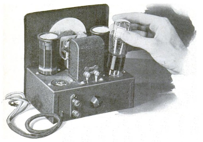
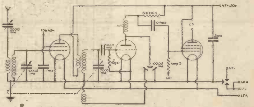
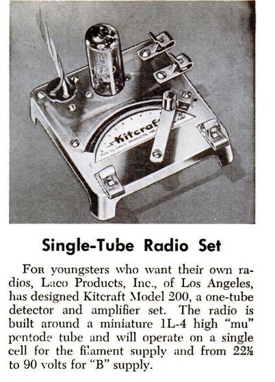
1937 Two Tube Regen

1937FebPS02Eighty five years ago, the February 1937 issue of Popular Science carried the plans for this two-tube regenerative receiver for the broadcast band up to 65 meters (about 4.6 MHz) with two plug-in coils. The set used two type 49 tubes, with the first one reflexed to serve as both RF and AF amplifier. The second tube served as regenerative detector.

The remarkable part of this receiver was that the B+ was only 11 volts. It used two dry cells for the filaments, which were also hooked in series with a 7.5 volt battery. The magazine noted that this made the receiver ideal for portable use, since the batteries were small enough to be carried in a pocket.

1937FebPS03


U.S. Observes War Time: 1942

1942Feb23LifeEighty years ago today, this picture appeared in the February 23, 1942, issue of Life magazine, taken at 2:00 AM on February 9, 1942. The country had just switched to War Time (year round daylight savings time), and as a result, the railroad men of the Rocky Mountain Rocket, an express train of the Rock Island Line moved their watches ahead one hour. To keep the trains in synch, the train came to a stop for an hour one mile west of Menlo, Iowa. A view of the same stretch of track today looking west, courtesy of Google Street View, is shown below.

Shown in the photo of the eastbound train are engineer E.V. Coleman, fireman L.E. Durbin, conductor Fred Lykke, brakeman A.O. Smith, and foreman F.H. Sprenger.

MenloIowa


1942 Three Valve Emergency Receiver

1942FebPracWirelessEighty years ago, the January and February 1942 issues of the British magazine Practical Wireless showed the construction details for this three tube emergency receiver. The magazine had received many demands for a receiver capable of good performance on the medium waves, but with components that could be obtained with a minimum of difficulty, given the wartime conditions. The editors settled on this three tube design, with one tuned RF stage, which was found to perform adequately, but “shorn of refinements which would normally have been incorporated in times when components were easily and quickly obtainable.”

The main design was published in the January issue, with the February issue showing some refinements that would make the set more sensitive and selective. The February issue also showed how a two-tube version could be made, which might be necessary due to wartime parts shortages.

The regeneration control on this set is interesting, and something I haven’t seen before. It is a variable differential capacitor, which has two separate stators, and one rotor. The idea is evident from the diagram symbol. They are also sometimes called a split stator variable capacitor, and they apparently are a thing.

1942FebPracWireless2


1957 Two-Tube VHF Superregen

1957FebPE31This young man is exploring the action bands of the VHF spectrum with a two-tube superregenerative receiver from the February 1957 issue of Popular Electronics.

The set tuned 28-175 MHz, which included the FM and TV bands, as well as amateurs, police, fire, and aircraft. The magazine noted that the layout of the circuit was critical, and cautioned builders to construct it according to the photographs, in addition to the schematic. In particular, short lead lengths in the RF stage were critical.

A 12AT7 served as RF amplifier and detector, with a 6AF4 serving as audio amplifier. A signal generator was suggested for final calibration, but in the absence of one, TV and FM broadcast stations could be used to figure out the dial positions. Three plug-in coils were used for band switching.

1957FebPE32


1922 Boys’ Life Receiver

1922FebBLA hundred years ago this month, wireless column of the February 1922 issue of Boys’ Life showed scouts how to put together the simple radio receiver shown here.  The magazine noted that just a few years prior, there was still little to hear on the airwaves in most of the country.  Near the coast, it would be possible to pick up Morse transmissions to and from ships, and in larger cities, there might be a few signals here and there.

But in most of the country, there had been little to listen to.  But that ways changing, and by 1922, just about anywhere in the country, there were plenty of interesting signals just waiting to be pulled in.  In fact, even in areas without newspapers, the radio could be used to pull in stories straight off the news services, and it was possible to get sports scores long before your neighbors could.  There were even concerts being listened to by hundreds of thousands of people in many states.


Illusion: Candle Burning in Bottle of Water

1937FebPS01For a simple illusion that can be part of a science fair project, this self-explanatory diagram shows how to make a candle look like it’s burning inside a bottle of water.

A plate of glass is placed as shown.  Since it allows light to pass through, but also reflects light, when it’s viewed at the correct angle, it appears that the candle is inside the bottle of water.

This idea appeared 85 years ago this month in the February 1937 issue of Popular Science.


1937 Grocery Prices

1937Feb18PghPostGazette

For a snapshot of grocery prices 85 years ago today, this ad appeared in the Pittsburgh Post Gazette on February 18, 1937. At first glance, the prices look like bargains, but the Great Depression was in full force, and for many, there wasn’t a lot of money to go around. According to this online inflation calculator, one dollar in 1937 was the equivalent of $19.36 today. For round numbers, let’s call it $20, so spending a nickel in 1937 would be about the same as spending a dollar today.

Some things were cheaper then. For example, for the ground beef, veal, or pork, you would need to hand over ten nickels, so the three pounds is the equivalent of about $10 today, or about $3.33 per pound.  How does that compare to today’s price, which you can find on Amazon at this link.

On the other hand, three pounds of coffee for 75 cents sounds like a bargain until you realize that’s five nickels per pound, or the equivalent of $5 per pound today. To compare, you can find the current price at Amazon at this link.

Potatoes were a nickel a pound, meaning that they were the equivalent of a dollar a pound today. Eggs were three dozen for 89 cents. What would that be in today’s money, and how much would those same eggs cost today?  You can find out at this Amazon link.

Surprisingly, duck was cheaper than chicken.  Duck was 25 cents per pound, but chicken was 29 cents.   If you don’t want to cook, you can eat in the store’s cafeteria. Lunch for two people was 54 cents, and a five-course dinner with table service was 75 cents each.


Some links on this site are affiliate links, meaning that this site earns a small commission if you make a purchase after clicking the link.

TV Relay Tower, 1952

1952FebRadioElecI remember as a kid seeing a structure similar to this one. I don’t remember exactly where, but it was somewhere along the route between Minneapolis and Duluth, with one horn facing south, and the other facing north. I asked my parents what it was, and they said it was for relaying TV signals. It made perfect sense to me, since the two horns looked a lot like TV screens.

I didn’t know what was inside, but now I do. The electronics were on the top floor, the B+ power supply was on the third floor, the filament power supply was on the second floor, and a backup generator was on the ground floor.

This diagram appeared 70 years ago this month in the February 1952 issue of Radio-Electronics.  Click on the image to see the full size version.