Monthly Archives: September 2020

1960 Carrier Current Pager

1960SepPESixty years ago this month, the September 1960 issue of Popular Electronics showed how to put together this one-way carrier current intercom. It could be used to listen to the nursery, garage, or other room, anywhere in the house. The transmitter was a simple one-transistor oscillator, using a speaker as the microphone. It sent the signal through the house wiring to another room, where a pickup coil was plugged in and placed near a radio set to a clear spot at the bottom of the dial. Despite the low power, this hookup allowed the signal to be monitored anywhere in the house.

According to the magazine, the parts cost was about $10.

1960SepPE2


1970 Soviet Crystal Sets

1970SepSovietXtalSetIn September 1970, I was probably busy putting together crystal sets. And some things are universal, and it appears that my counterparts behind the Iron Curtain were busy doing just the same thing. These illustrations are from the September 1970 issue of the Soviet publication Юный техник (Young Technician).

Interestingly, my Soviet counterparts were able to buy a suitable inductor, whereas I had to wind mine on a toilet paper tube. I suppose toilet paper shortages might be the logical explanation. In any event, the Soviet kids were able to pull in their strong local stations, just like I could.

The other illustration below isn’t too different from some of my experiments.  From the bottom figure, it appears that the Soviet kids figured out, as I did, that if you used two wires from a transistor, that would work about the same as a diode.

1970SepSovietXtalSet2


1980 Metal Detector

1980SepEEThis young woman is seeking her fortune with a metal detector she put together herself, according to plans contained in the September-October 1980 issue of Elementary Electronics (which had recently merged with Science & Electronics, as noted on her shirt). The article mentioned that the biggest downside of the treasure hunting hobby was the amount of money needed for the equipment, which often exceeded the value of the treasure. But this inexpensive circuit, which could run for a year on a single 9 volt battery, was a good tradeoff between economy and sensitivity. The set was able to locate a penny buried 3-5 inches deep.

The circuit included three inductance coils, two of which were balanced to have a net current of zero passing through them. When a piece of metal came within the field, the inductance of one coil changed, causing the circuit to oscillate. The circuit consisted mostly of an integrated circuit audio amplifier which was wired up to oscillate when the inductance was just right.

The article cautioned treasure hunters that practice was the key, and they should see how the instrument reacts to various pieces of treasure given local soil conditions.

1980SepEE2


1940 Two Tube Regen

1940SepPSgThe young man shown above is now close to being a centenarian, but 80 years ago, he was buying some radio parts from his friendly local radio dealer. He was going to get his money’s worth out of those parts, since he planned to re-use all of them in several different projects, the first of which appeared in the September 1940 issue of Popular Science.

1940SepPShThe total expenditure for all of the projects would be $8.95, and this month, he was purchasing a number of components, including two tubes, a pentode-triode 25B8GT and a pentode-rectifier 70L7GT. This month, he was going to make the two-tube receiver shown below. This month, only one half of each tube would be used. The 70L7GT served as rectifier, and the pentode section of the 25B8GT was regenerative detector. In future months, the circuit would become more elaborate.

The article noted that the capacitors could be soldered in place, but since the resistors would need to be moved around, it was best to attach them using clips so that the leads would be preserved.

The parts list reveals that this version of the set would tune 100-570 meters, meaning that it would cover the standard broadcast band, plus a few interesting signals higher in frequency.

1940SepPSi


1940 One Tube Superregen Pocket Portable

1940SepPSaEighty years ago, this radio enthusiast/sports fan was able to attend the game and listen to the play-by-play broadcast from the stands, thanks to this one-tube pocket portable, described in the September 1940 issue of Popular Science. The set was billed as being only a little larger than a tobacco tin, and was constructed from cigar box wood. The antenna was a loop wound around the box, and it was said to be able to pull in stations up to fifty miles away.

The circuit was superregenerative, and used a miniature 958 tube, which is likely unobtainium today. The B battery consisted of four penlite cells, and the A battery was a normal flashlight battery.

1940SepPSb1940SepPSc


Hammarlund Receiver at WCCO-TV, 1970

1970SeptHamRadioShown here in this Hammarlund ad from the September 1970 issue of Ham Radio magazine is part of the equipment of WCCO-TV in Minneapolis, whoss transmitter was then located in the Foshay Tower. The station had a Hammarlund HQ-180-AX receiver mounted on the rack as part of its frequency measuring equipment. The receiver was used to tune in WWV to zero beat the station’s calibrator. Then, signals were received on the receiver and beat against that calibrator.

The receiver was also used to check the tuning of transmitter multiplier stages, to receive time checks from WWV, and as a backup Emergency Broadcasting System receiver.

Shown in the picture is transmitter engineer Stan Allison, and the letter to Hammarlund describing the setup is penned by transmitter supervisor Gerald King Ellison.


Marianne Brown, 2AOA

1920SepRadioNewsA century ago this month, the cover of the September 1920 issue of Radio News featured this man teaching the art of radio to his companion.

1920SepRadioNews2The issue also featured an article by Marianne Brown, 2AOA, whom we profiled in an earlier post, from the magazine’s April 1920 issue. Her training was much more formal than the woman shown on the cover. With the U.S. in the war, she decided to do her part by getting trained as a radio operator, and then waiting for the government to put her to work. Unfortunately, that never happened, but she did secure a position in the testing department of the Marconi Company, and she writes about her experiences there as “one of the gang.”


1960 Two Transistor Portable

1960SepRadioElecThe plans for this 2-transistor pocket portable receiver appeared in Radio-Electronics magazine 60 years ago this month, September 1960. The circuit was the result of prodding from the author’s son to produce a pocket radio in time for the World Series, hence the name of the set, the World Series Special.

The author noted that pocket portable typically came in two categories–they were either superhets that were difficult and expensive to build, or else simple one or two transistor sets that wouldn’t pull in anything without a 50 foot outdoor antenna. This set was a good compromise, since it would pull in the strong local stations (presumably including the one that was broadcasting the World Series) without an external antenna.

The circuit had a regenerative RF stage, followed by a crystal detector. That was followed by two stages of audio amplification. It used two transistors, the venerable 2N170 NPN, and the 2N107 PNP. The 2N170 was reflexed to serve as both RF amp and first AF stage. The 2N107 was the final audio transistor. The article stressed the importance of using a good earpiece, since a sensitive one would have much better volume. Regenration was fixed, and there was a separate volume control. It was powered with a 7.5 volt mercury battery that was soldered in place, since the author apparently had faith in his son to turn the radio off when not in use.

The author noted that layout was not critical, with one exception: It was important to keep the battery as far away as possible from the antenna coil.

1960SepRadioElec2


Using Dual-Filament Light Bulb as Rectifier or Detector

Converting dual-filament lamp to diode tube
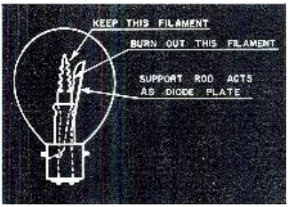
We previously featured the idea shown at left, using a dual-filament light bulb as a diode tube.  The idea is to burn out one of the filaments, and use that as the plate.  The other filament becomes a directly heated cathode.  This is from the January 1943 issue of  Radio News, which also included other ideas for emergency crystal sets.  This one called for a 6-volt type 1158 lamp, which is still available on Amazon, although the same idea could be used with a 12 volt type 1157, which is available at at Amazon or WalMart.

1920SepPS
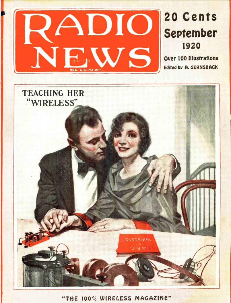
The same idea appeared a hundred years ago this month in the September 1920 issue of Popular Science.  This one was to use the bulb as a rectifier and not detector, but the idea is the same. The idea was sent to the magazine by one R.U. Clark, 3d:

The bulbs used as rectifiers are the bayonet-base type, round automobile headlights of the double-filament type, just recently put on the market for the Ford automobile. One filament should be burned out by an over-voltage current applied to the proper terminals. The connecting wire and all that remains of this filament can then be used as the plate, and the remaining filament, which consumes only .85 amperes, can be used to supply the electron stream.

The usual alternating current can be fed to the filament and plates of these bulbs when suitably reduced by transformers, and direct current taken out in the manner usual with such devices.

These tubes will pass about 0.5 amperes each under suitable conditions.

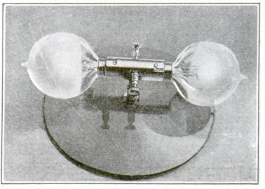
The author notes than many want to experiment with vacuum tubes as rectifiers, but don’t want to run the risk of damaging expensive tubes. The Ford light bulbs, on the other hand, sold for only 65 cents, making such experiments more forgiving. The illustration here shows to bulbs, presumably mounted as a full-wave rectifier.

Making a homemade vacuum tube in this manner would make a very interesting science fair project.  To demonstrate, an old “wall wart” transformer could be used as the input.  Most have a DC output, but some have a low voltage AC output.  Examine the ones available at the closest thrift store, and chances are, a suitable one can be found.  By using an inexpensive multitester that measures both AC and DC voltage, it can be shown that the input is AC and the output is DC.
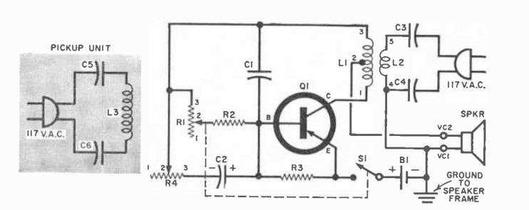
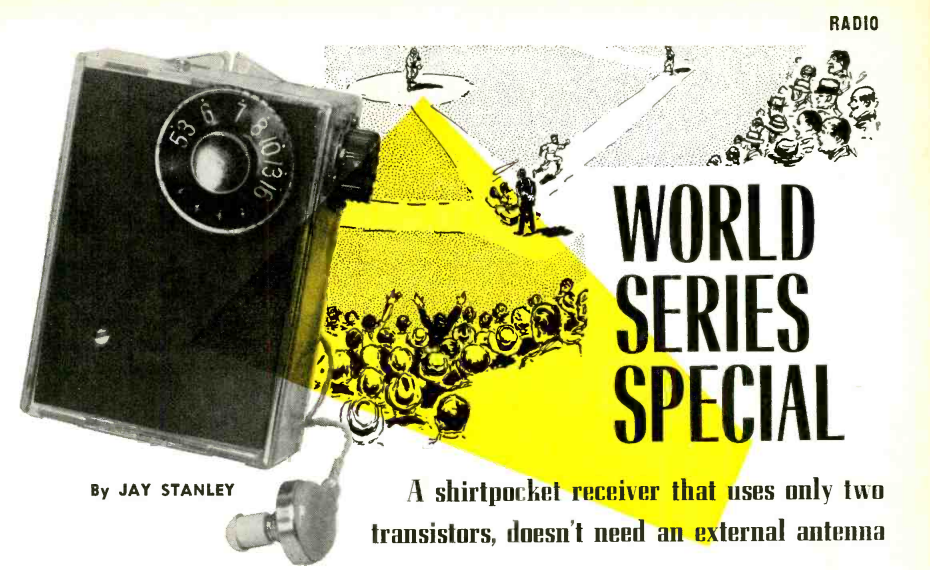
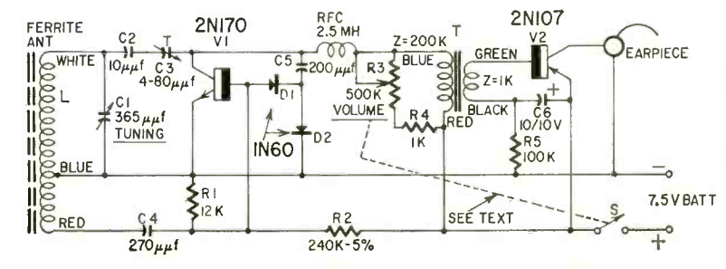
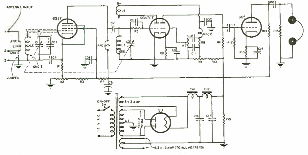
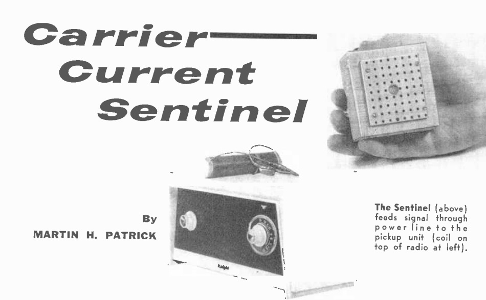


1945 Three Tube Regen

1945SepRadioNewsThis handsome 3-tube shortwave receiver was put together during the war by Harry D. Hooton, W8KPX, as reported in the September 1945 issue of Radio News.  He reported that at the outbreak of war, he sold his receiver and other equipment to the U.S. Army Signal Corps. But before long, he had the urge to build something, and this set was the result. He was able to find many of the parts in his own junk box, and acquired others by very carefully negotiated trades with other local hams.

The set covered 2-20 MHz with three plug-in coils. It used three tubes, plus one rectifier in the separate power supply. Hooton reported that he constructed the power supply separately to avoid hum in the high-gain audio stage, and also to make the set usable with batteries if desired at a later time.

The set used a 6SJ7 as RF amplifier, followed by a 6SN7, a dual tube used for regenerative detector and audio amplifier. This went to a 6C5, which was a second stage of audio amplification.

1945SepRadioNews2