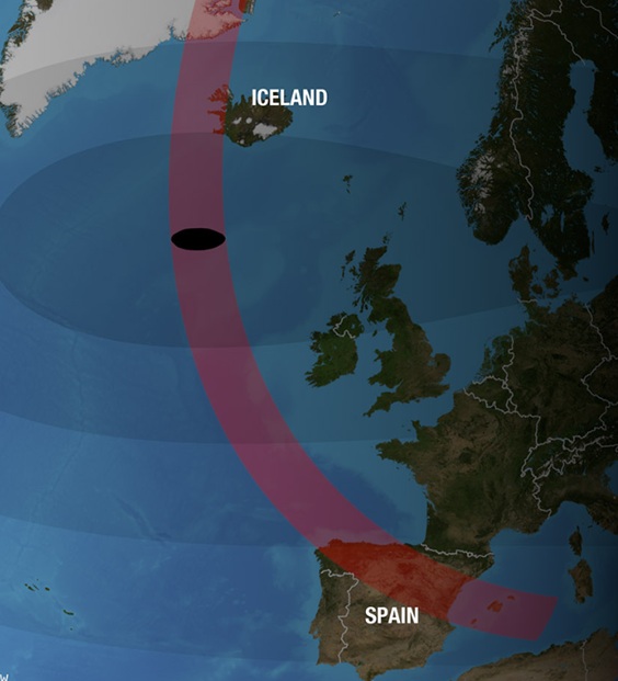
The next total solar eclipse will take place on August 12, 2026. The path of totality passes through Greenland, Iceland, Spain, and a tiny piece of Portugal. You can see it as the black dot on the animation at left, and in the path of totality shown above.
Seeing a total solar eclipse from within the path of totality is a once in a lifetime experience. If humanly possible, you want to take yourself and your kids there to see it! Please note that even a few miles away from this band, it’s an interesting phenomenon, but nothing even close to actual totality. Don’t let anyone convince you that, for example, a “99% eclipse” is almost as good. The truth is that the 99% eclipse is millions of times brighter than a total eclipse. If you turn a light switch 99% of the way to off, the light is still on. And eclipses work the same way. If you are in Europe, you owe it to your kids to take them to see the eclipse. When I ask students who have visited the path of totality during a North American eclipse, I ask them if it’s the coolest thing they’ve ever seen. Invariably, they say yes.
Our original plan was to travel to Spain to view the eclipse (as we did in 2017 and 2024 in North America). Unfortunately, that didn’t work out this year. But for Western Europeans, it will be the first chance since 1999, when a total eclipse was visible in the UK, France, Belgium, Germany, Austria, Hungary, and Romania.
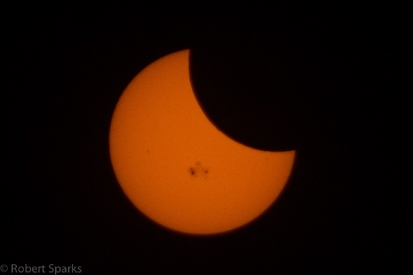
What is overlooked this time is that the eclipse will be visible in North America. It will be visible in Alaska, Canada, and most of the northeastern United States. It’s only a partial eclipse, and as noted above, a partial eclipse isn’t a spectacular cosmic event like a total eclipse. But it’s still an interesting phenomenon, and worth viewing if you live there anyway.
To view a partial eclipse safely, you will need eclipse glasses. Our sister site, MyEclipseGlasses.com, has them available. We also have them for sale at retail locations in England and Spain.
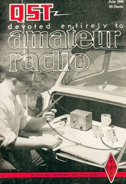
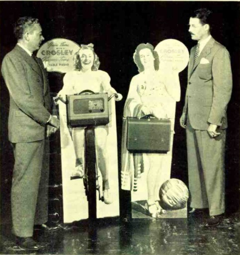
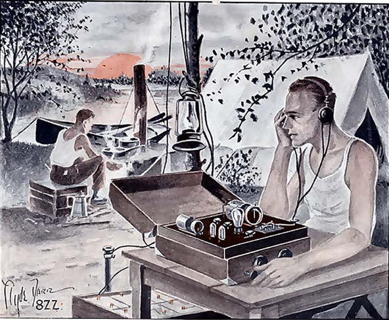 One hundred years ago this month, these proto-POTA hams were on a camping trip, and their natural inclination was to bring along a rig and make a few contacts.