Monthly Archives: January 2018

1938 Helium Controversy

1938LifeJan31Eighty years ago today, the January 31, 1938, issue of Life magazine carried the feature shown above regarding the proposed sale of U.S. helium to Nazi Germany.

In the wake of the Hindenburg disaster earlier in the year, the Germans realized that for their lighter-than-aircraft industry couldn’t recover if they continued to use hydrogen.  Unfortunately for them, the United States was the sole source of the gas.  They ultimately prevailed upon the Roosevelt administration to supply it, and the president ushered a bill through Congress to allow the export of the strategic material.

1938LifeJan31a
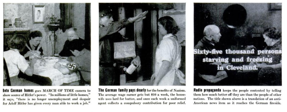
Of course, sale of helium to Germany meant sale of helium to the Nazis.  And the very next page of the magazine (probably not a coincidence) had something to say about Nazis.  The magazine’s “Movie of the Week” was a newsreel, an edition of The March of Time, entitled “Inside Nazi Germany-1938.” Some of the scenes of that movie are shown here. The magazine noted that the film was initially banned by the Chicago Police Board of Censors, on the ground that “it might offend a friendly nation.” But after a press outcry, the ban was lifted.

Some additional scenes from the movie are shown below:

1938LifeJan31b

Ickes.gif

Harold Ickes. Wikipedia photo.

The helium sale never went through. Germany annexed Austria on March 12, 1938.  Notwithstanding this event, most of the Roosevelt administration was keen on proceeding with the sale.  However, since the helium originated on federal lands, the power to go forward was vested in Interior Secretary Harold L. Ickes.  After the annexation, he vetoed the sale, despite opposition by both the President and Secretary of State Cordell Hull.

Ultimately, the Solicitor General sided with Ickes, ruling that the Secretary of State had the ultimate power to allow or decline the sale.

An excellent history of the controversy can be found at this 1964 University of Arizona Master’s Thesis by James Walsh.


1948 One Tube Broadcast Set for Beginners

1948JanPM31948JanPM4Seventy years ago this month, the duo shown here are working on a one-tube broadcast set shown in the January 1948 issue of Popular Mechanics.  The set used a dual 6SL7 tube as regenerative detector and audio amplifier.  It was built on a wooden ladder-style chassis, allowing the tube and coil sockets to be mounted neatly without need of any drilling.

The set was the first in a series of progressive receivers.  As later issues of the magazine came out, the parts could be re-used to make more complex designs.

1948JanPM5


Three 1943 One-Tube Receivers

1943JanRadiocraft1

The January 1943 issue of Radio Craft magazine contained the plans for no less than three one tube receivers, the first of which is the unusual looking set shown above, dubbed by the magazine as the “Simplicity 1.”

In addition to being designed around the concept of simplicity, the set dealt with parts shortages. In particular, variable capacitors were hard to come by. Therefore, tuning was accomplished with a “capind,” a component which combined capacity plus inductance. In other words, it was a combined variable capacitor and variable inductor, all in one component.

The “capind” consisted of a coil carefully wound over a wooden dowel, covered by an extremely thin paper sleeve. That was covered by a piece of tin foil, which served as the capacitor. The assembly is shown below:

1943JanRadiocraft2

1943JanRadiocraft3The set was regenerative, and the young woman in the photo above is adjusting the regeneration by adjusting the “throttle” condenser, which is a homemade tubular capacitor.

With the use of these homemade parts, the cost of the set (not including 1G6G tube and batteries) was said to be less than a dollar.

1943JanRadiocraft4The second set featured by the magazine, shown at right, is slightly more advanced, contains a conventional tuning capacitor, and was capable of tuning the short wave bands through the use of four plug-in coils.

This set employed the same 1G6G tube, and used a variable resistor to adjust regeneration.  The use of a 35-75 foot antenna was recommended.

1943JanRadiocraft5


Finally, in response to requests by “several readers,” the magazine reprinted the schematic of the “Pigmy Receiver” which had originally appeared in the magazine’s June 1940 issue. This set used a single 117L7, one half of which served as rectifier, with the other half serving as detector.

You will note that only one wire is connected to the line cord, which the magazine describes as a “Safety First” method of plugging it in. The other power connection is through the thoroughly grounded chassis. With the cord plugged in the wrong way, the set would not light. Of course, this circuit would trip a modern ground fault interrupter circuit, but it would be a relatively safe way of operating a radio directly off the line current.

1943JanRadiocraft6


1958 Boys’ Life 3-Transistor Regen


1958JanBL1958JanBL1The January 1958 issue of Boys’ Life magazine carried the third part in a series about shortwave listening, and included the plans for the three-transistor shortwave receiver shown here. The construction article was authored by Howard McEntee, W2SI, who was also the designer of the magazine’s 1956 CONELRAD receiver.

The shortwave set covered 1.25 to 18.5 MHz with four plug-in coils, meaning that it could tune the top of the broadcast band, several shortwave broadcast bands, and the 160, 80, 40, and 20 meter ham bands.  It employed a 2N1114 as the regenerative detector, followed by two CK722‘s for audio amplification to drive a pair of headphones.  It was powered by four penlite cells, which were said to provide several hundred hours of use.

Tuning was accomplished with two variable capacitors, one for broad tuning, with another for bandspread for carefully tuning a crowded band.  A third variable capacitor was used to adjust regeneration.

The article cautioned that this set wasn’t necessarily for beginners.  It advised that those who had never built a radio before should start with a more simple set and then graduate to this one.  “Real care is needed in wiring, for a wrong connection in some parts could mean immediate ruin of over $10 worth of transistors, the finished job shoujld be checked and rechecked, before the power is turned on.”


1958JanBL2


1952 and 1954 Solar Eclipses

SovietEclipseCoverMillions of Americans were able to witness the Great American Eclipse of 2017 or will be able  to see the eclipse of April 8, 2024.  The 2017 eclipse crossed the United States from northwest to southeast, and the 2024 eclipse will run from southwest to northeast.  The Soviet Union had a similar pair of eclipses on 25 February 1952 and 30 June 1954.  The intersection of the two American eclipses is near Carbondale, Illinois.  The paths of the two Soviet eclipses had their intersection at a point in northern Iran, just south of the Caspian Sea.

SovietEclipseMap

The illustrations shown here are from a Soviet booklet published in 1950.  In addition to discussing solar and lunar eclipses generally, it contains information about the two Soviet eclipses of the 1950’s, including the map shown above.  It also contains a table showing all total solar eclipses worldwide through 1999.

The booklet, Солнечные и лунные затмения (Solar and Lunar Eclipses) by Prof. A.A. Mikhailov, part of the series Научно-популярная библиотека (Popular science library), reveals that the path of the 1954 eclipse came very close to a number of Soviet cities, including Kaliningrad, Vilnius, Minsk, Kiev, Rostov, and Baku.   The 1954 eclipse had also been visible in the United States, starting at sunrise in Nebraska, and passing over South Dakota and Minnesota (including Minneapolis and St. Paul).  It then passed over Canada, Greenland, a tiny portion of Iceland, Norway, and Sweden, before entering the Soviet Union near Kaliningrad.

The 1952 eclipse, after passing over Africa, went over a less populated area of Turkmenistan, Uzbekistan, Kazakhstan, and Asiatic Russia.

This video shows the 1954 eclipse from Minneapolis:

This page contains a reminiscence and photo of the same eclipse from Kiev.  The Google translate function does an admirable job of making it readable in English.

One of the scientific observations made during the 1954 eclipse was the measurement of radio emissions by the sun on various frequencies, documented in this 1955 article in the journal Astrophisica Norvegica, vol. 5, p. 131.  The graph below shows the signal as received in Vesterøya, Norway, on 200 MHz.  As would be expected, the solar noise reaches a minimum value at the time of total eclipse.

1954EclipseRadio

Information on how to form a Minnesota LLC.


1933 Crystal Set with Piggly Wiggly Detector

1938JanTVNews

1938JanTVNews1Shown here is a very basic crystal set mounted in a tobacco can, as shown in the January 1933 issue of Television News.

The design for this well-constructed little set apparently originated in a Danish magazine, and was adapted by one Clifford E. Denton, who put it together in a couple of hours one evening. The variable capacitor, shown as C1 in the close-up picture here, was a compression type. The plates did not rotate. Instead, the screw was turned to compress the capacitor, with an insulating material to keep the plates from shorting out. This component was known as a “variodensor.” The coil could be purchased, or made at home on a wooden form.

The most notable feature of this set was the fixed detector, bearing a brand name that apparently never quite made it in the world of radio. The detector was a “Piggly Wiggly crystal detector.” The magazine described the Piggly Wiggly as “much better than the old-fashioned open detector, the crystal itself and the cat-whisker being enclosed in a neat molded bakelite case.” It could be adjusted by means of a “little red button” on the outside.

1938JanTVNews2


1928 Soviet Crystal Set & Galvanometer Experiments

1928No1RadioLThis illustration of a handsome crystal set listening post comes from 90 years ago, in 1928 issue number 1 of Радиолюбитель (Radio Amateur) magazine, illustrating an article by A. Pushkov.

Elsewhere in the magazine, it’s apparent that, just like their Western counterparts, young Soviet experimenters discovered the fun that could be had with a milliammeter, although I have to admit that I never thought to conduct the second and fourth experiments shown here:

1928No1RadioL11928No1RadioL2

(The piece of metal in the above diagram is marked “железо”, iron.)

1928No1RadioL31928No1RadioL4

The sensitive galvanometer was probably a valuable instrument in the 1928 Soviet Union.  Modern students desiring to reproduce these experiments can do so very inexpensively with a digital voltmeter such as the ones shown here:


1944 Toy Phonographs

1944SearsToyPhonoI was a little bit surprised to see these phonographs for sale in a wartime catalog, but they are shown here in the 1944 Sears Christmas catalog.

They’re surprising for a couple of reasons.  First, they’re an interesting juxtaposition of an acoustic phonograph with an electric motor.  I assumed that acoustic phonographs were wind-up models, and that electronic phonographs had an electric motor.  But there’s no reason why there can’t be some overlap..

But I was more surprised to see phonographs for sale, despite the fact that the manufacture of phonographs had ended by order of the War Production Board (WPB) on April 22, 1942.  It’s unlikely that there was much old stock left in the Sears warehouse at that point (although it’s not at all unlikely that there were electric phonograph motors left over when the ban went into effect).

Interestingly, these are not being sold as phonographs.  They are being sold as toy phonographs.  I’m not aware that the WPB made an exception for acoustic phonographs.  But apparently, they did make an exception for toy phonographs.

The model on the right looks like a toy, especially with the decorations.  But the model on the left doesn’t really look like a toy.  It looks more like just a low-end portable phonograph.  I suspect that more than a few were sold, not for the kids, but because it was the only new phonograph people were able to buy.

The video below shows a similar instrument manufactured, surprisingly, as late as 1974:


International Grid Chase Update

GridMap0122As I previously posted, during 2018, the ARRL is conducting an Amateur Radio event known as the International Grid Chase. The event is a friendly competition to see who can work the most grid squares on any band or mode.

A grid square is a division of the earth into sectors one degree latitude by two degrees longitude. Each one is designated by a four character identifier. For example, I live in EN34

After I wrote my previous post, the official rules for the event were announced. And contrary to my initial interpretation, it is important to work grids on as many bands and modes as possible, since points are awarded for each grid on a new band or mode.

With my modest station, I’m certainly not in the big leagues. But with a very modest effort, I now have 100 grids confirmed, as shown on the map above. And because I have some of them confirmed on more than one band or mode, I have a total of 162 points, placing me in about 1953rd place out of 17287. That places me in about the top 11%, which I consider to be respectable given a modest station and limited time.

Interestingly, on a later update of the Leader Board shortly after writing this, I see that I am now tied with W1AW for 1928th place.  Strangely enough, this is the second time I’ve been tied with the ARRL’s Headquarters station:

0122LeaderBoard

Points are awarded as the contact is confirmed on Logbook of the World (LOTW). Since confirmations continue to filter in, this score will continue to rise.

Most of my contacts so far came from two contests, the CW and SSB weekends of the North American QSO Party. A majority of contesters seem to participate in LOTW. Therefore, by making as many contacts as possible, the score continues to rise. As you can see from the map above, most of my contacts are from the United States, with a smattering of contacts from Canada, Mexico, and the Caribbean. The handful of European contacts I’ve made so far have not yet confirmed on LOTW.

So far, I have no digital contacts. So at the very least, I’ll need to get set up for PSK31, which requires only very minimal hardware between the computer and radio. Every contact I make will be worth one point, since I have yet to work any grids in a digital mode.

Two upcoming contests are worthy of note. Next weekend is the Minnesota QSO Party, which has participation in all or most Minnesota counties. It will be a good opportunity to get the 26 grids which lie completely or partially in Minnesota. Other state QSO parties later in the year will provide similar opportunities.

And the ARRL DX Contest (CW in February and SSB in March) will provide a lot of new grids, since almost everything outside the U.S. will be new for me.

To follow your own progress, a good tool is the N1KDO Grid Mapper, which was used to generate the map at the top of the page. When I started as a Novice, one common activity for new novices was to color in a “Worked All States Map,” which was nothing more than an outline map of the United States. The process of coloring in a map can be addictive, and I often find myself refreshing the map to see if other confirmations have come in, with another square turned red.


The DX Hounds Are Back, 1948

1948JanBLSeventy years ago this month, the January 1948 issue of Boys’ Life magazine let its readers know that after a wartime absence, amateur radio was back, and that the DX Hounds were back. The article began with the story of how an Ohio ham, former Navy radio operator Paul L. Hughes, saved 300 in New Mexico. One night, Hughes heard a call on 10 meters from a motorist stranded in a snowstorm with 300 other motorists in New Mexico. Hughes found a ham in Albuquerque who phoned the New Mexico State Police, who had a rescue party on the way 26 minutes after the call for help.

For scouts interested in getting started, the article recommended three books, How to Become a Radio Amateur and the License Manual from the ARRL, as well as, of course, the Radio Merit Badge pamphlet. Each was available for 25 cents from the respective publisher.