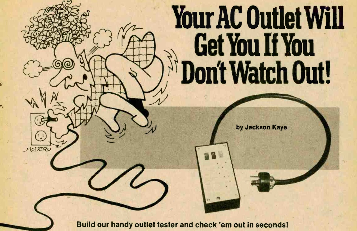
 If you do any electrical work around the house—or even if you don’t, and you just want to make sure the electrician did things right—you really ought to have an inexpensive outlet tester in your toolbox. You can plug one in and tell at a glance whether the receptacle is wired correctly, or if there is some invisible and potentially hazardous fault hiding behind the faceplate.
Those errors can include reversed polarity, an open neutral, a missing safety ground, or a hot wire that’s not hooked up at all.
Fifty years ago, fifty-cent molded plug-in testers weren’t sitting in blister packs on the counter of every hardware store. If a home handyman or experimenter wanted one, he often had to build it himself.
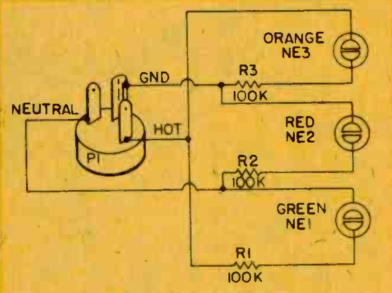
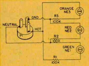 The circuit shown here appeared in the September-October 1976 issue of Elementary Electronics. As you can see, the design is deceptively simple. It uses three neon lamps (NE-1, NE-2, and NE-3), each in series with a 100kΩ current-limiting resistor, bridged across the three conductors of a standard grounded three-prong plug:
- NE1 (Green) is connected between Hot and Neutral.
- NE2 (Red) is connected between Neutral and Ground.
- NE3 (Orange) is connected between Hot and Ground.
When plugged into a correctly wired 120-volt receptacle, line voltage is present across Hot and Neutral (lighting the green lamp) and across Hot and Ground (lighting the orange lamp). Because Neutral and Ground are tied together back at the service panel, there is zero potential between them, leaving the red lamp completely dark.
If you see the red lamp light up, or if one of the others fails to illuminate, you know immediately that something is miswired. If you want to build your own, it’s a quick weekend bench project using a handful of NE-2 neon lamps, three 100k ohm resistors, and a replacement 3-prong plug.
Of course, these days you don’t have to warm up the soldering iron just to check your wall outlets. You can pick up a ready-made commercial receptacle tester for just a few dollars. Modern versions use the exact same three-lamp bridge circuit inside, though most also include a built-in push button to test GFCI outlets. And, of course, unless you happen to have the parts in your junk box to start with, the cost of the commercial product will probably be a lot less than what you would have to pay to build your own. By the way, the colors of the neon lamps are not necessarily standard, so the color code shown in the 1976 version probably won’t match up with the modern product.
Some links on this site are affiliate links, meaning that this site earns a small commission if you make a purchase after using the link.

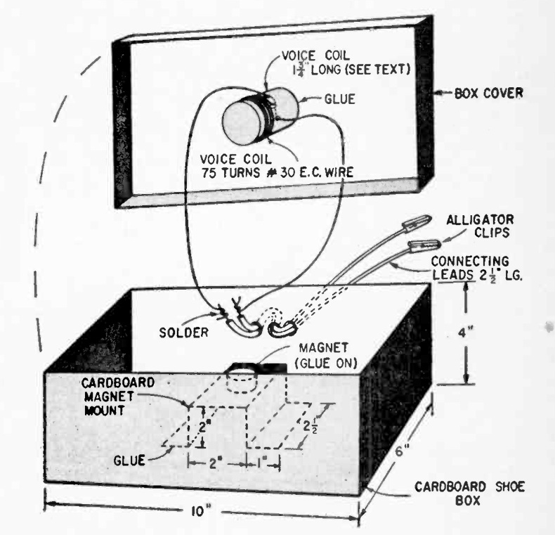 Sixty years ago this month, the October-November 1966 issue of Radio-TV Experimenter showed how to make this homemade speaker. It suggested that it would be an excellent science fair project, aimed at the 7th or 8th grade level. In addition to building the speaker, experiments can be done comparing it to a factory-made speaker.