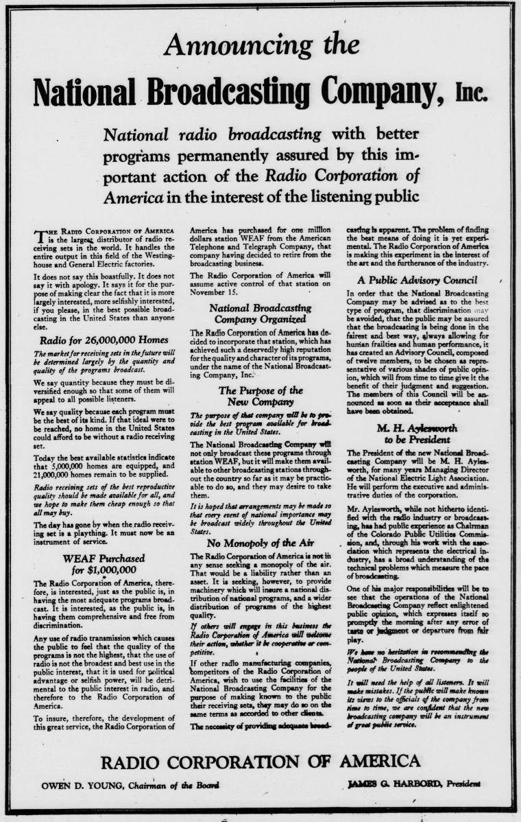
 A century ago today, Radio Corporation of America (RCA) took out full-page advertisements in newspapers across the country, including this one in the September 13, 1926, issue of the Washington Star, to make a historic announcement: the formation of the National Broadcasting Company (NBC).
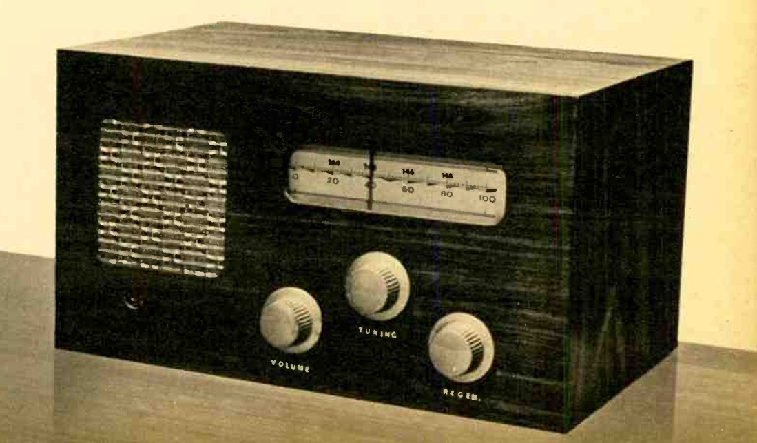
By 1926, an estimated 5,000,000 American homes had radio receivers, representing an audience of roughly 21,000,000 listeners. But as the ad candidly pointed out, the market was running into a fundamental economic problem. RCA was in the business of manufacturing and selling receiving sets and vacuum tubes, but nobody would buy a set if there was nothing worth listening to on the air. Individual local stations could not afford the high cost of first-rate talent, symphony orchestras, and grand opera on their own.
To solve the problem, RCA purchased station WEAF in New York from AT&T for $1,000,000, leased the telephone company’s nationwide equalized long lines, and organized NBC as an independent service company owned jointly by RCA, General Electric, and Westinghouse. Former Syracuse postmaster and business executive Merlin H. Aylesworth was named president.
The manifesto made a point of addressing widespread public fears of a radio monopoly. RCA Chairman Owen D. Young and President James G. Harbord promised that the company would not monopolize the ether, invited other broadcasters to tap into the network’s programs, and announced an advisory council of prominent citizens to ensure the service operated in the public interest:
“The Radio Corporation of America is not in any sense seeking a monopoly of the air. That would be a liability rather than an asset… It is hoped that arrangements may be made so that every event of national importance may be broadcast widely throughout the United States.”
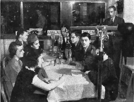
Two months later, on November 15, 1926, NBC made its formal on-air debut with a four-and-a-half-hour gala broadcast from the Grand Ballroom of the Waldorf-Astoria Hotel in New York, linking 24 stations across the country and launching the golden age of American network radio.
The stations carrying that first broadcast were:
- WEAF – New York, NY (Key Station)
- WJZ – New York, NY
- WEEI – Boston, MA
- WBZ – Springfield, MA / WBZA – Boston, MA
- WTAG – Worcester, MA
- WTIC – Hartford, CT
- WJAR – Providence, RI
- WCSH – Portland, ME
- WGY – Schenectady, NY
- WGR – Buffalo, NY
- WLIT / WFI – Philadelphia, PA (time-share)
- WRC – Washington, D.C.
- KDKA – Pittsburgh, PA
- WCAE – Pittsburgh, PA
- WTAM – Cleveland, OH
- WWJ – Detroit, MI
- WSAI – Cincinnati, OH
- KYW – Chicago, IL
- WGN / WLIB – Chicago, IL
- WOC – Davenport, IA
- KSD – St. Louis, MO
- WCCO – Minneapolis–St. Paul, MN
- WDAF – Kansas City, MO