I don’t envy the poor radio serviceman shown in the left illustration, in the June 1941 issue of Radio Retailing. That customer doesn’t look very happy. If the poor guy got drafted the next year, the drill sergeant couldn’t scare him any more than she did. She was going to miss her favorite programs for a few days, and it looks like she’s taking her wrath out on him.
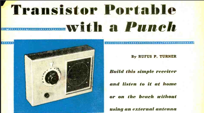
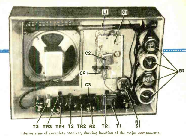
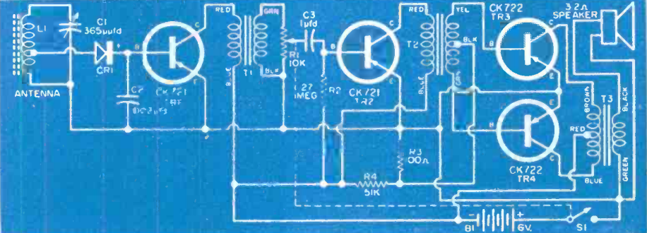
If you wanted to be the first on your block to have a transistor radio seventy years ago, one good way to meet that goal would be to build the one described in the May 1956 issue of Popular Electronics. It was said to pull in local stations with loudspeaker volume with no external antenna. It consisted basically of a crystal set followed by four stages of audio amplification.
Crystal sets often have very wide tuning, due to the detector loading down the tuned circuit and reducing the Q factor. In this case, however, the coil is tapped to reduce this effect.
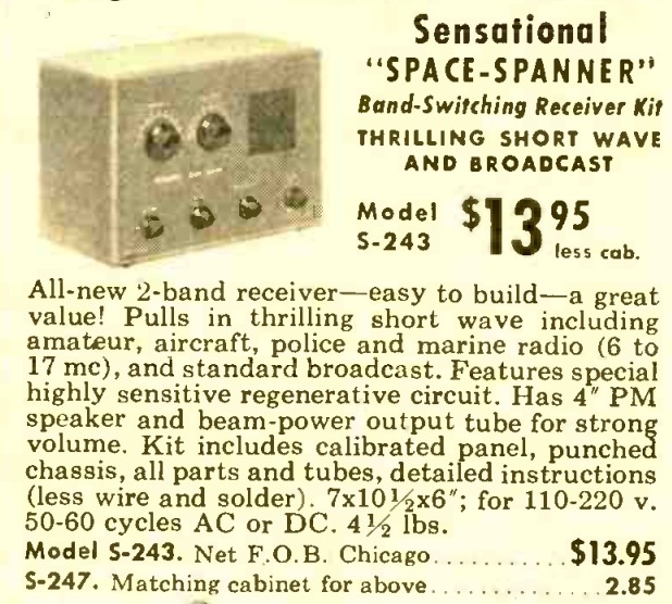
Seventy years ago this month, the May 1956 issue of Popular Electronics carried this ad for the Allied Knight Kit Space Spanner receiver. The three-tube AC-DC set covered the broadcast band and 6-17 MHz shortwave. It included a 35W4 rectifier and 50C5 final audio amplifier. The heart of the set was a 12AT7 which served as regenerative detector and first stage audio amplifier.
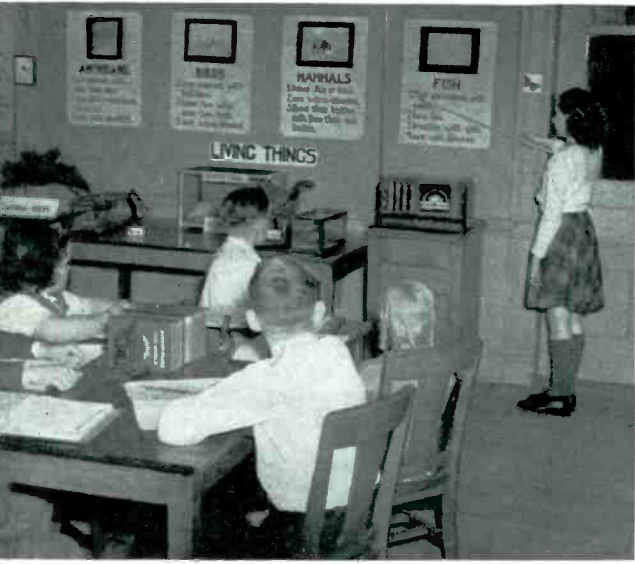
Eighty-five years ago, these Cleveland students are brushing up on the differences between amphibians, birds, mammals, and fish, thanks to their school system’s progressive use of radio in the classroom. It had been experimenting with radio since 1925, and was one of the first three (the others were San Francisco and Beattyville, KY) to get an FM license to broadcast to schools. The receiver was from Stromberg-Carlson, and the broadcast lessons were supplemented with these charts.
The photo appeared in the May 1941 issue of Radio Retailing.
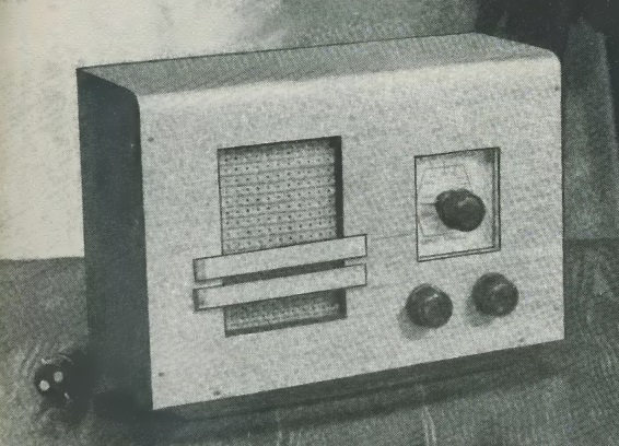
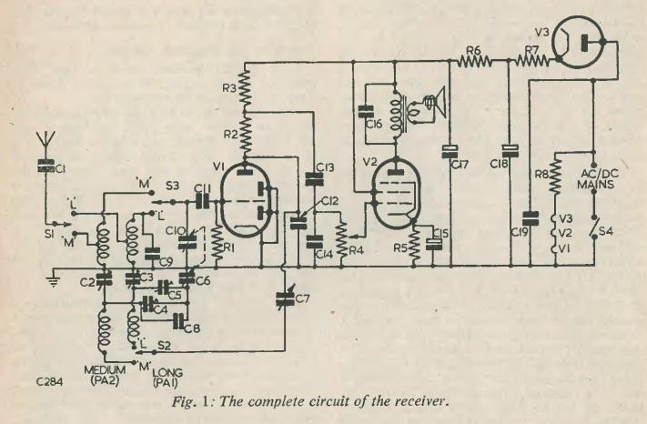
Seventy-five years ago this month, the May 1951 issue of Radio Constructor showed how to build this handsome three-tube (including rectifier) broadcast receiver. It covered both mediumwave and longwave (1225-2000 meters). A 15-foot antenna would pull in the mediumwave broadcasts, as well as the BBC Light Program and Radio Luxembourg on the longwave band. The detector was regenerative, and the author had to work out some tricks to keep the regeneration (or reaction, as they called it) stable even if the line voltage varied.
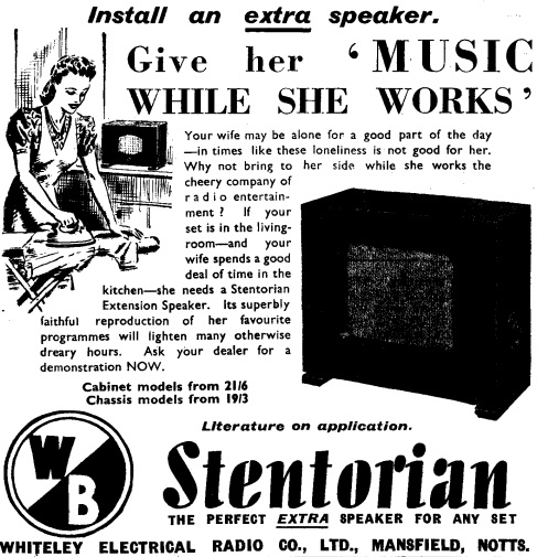
Eighty-five years ago, Britain was at war, but that didn’t mean that the British housewife couldn’t enjoy a little music while she worked. If your radio was in the living room, she was spending time working in the kitchen. The perfect solution was the addition of an extension speaker. She could then pass the otherwise dreary hours listening to her favorite programs. This ad for Stentorian speakers appeared in Practical Wireless, May 1941.
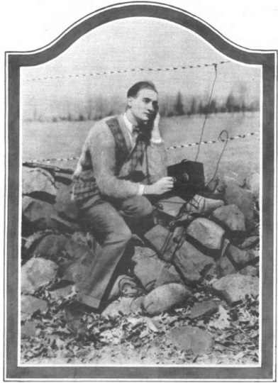
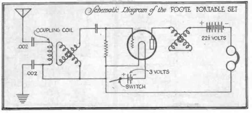
Shown here, one hundred years ago, is Brainard Foote, showing off the one-tube portable receiver, the details of which are contained in the construction article he authored in the May 1926 issue of Radio In The Home. He calls the set a Magic Music Box, and notes that it’s useful for picnics and outings. But it’s also useful for the traveling man, for information and entertainment in some distant city.
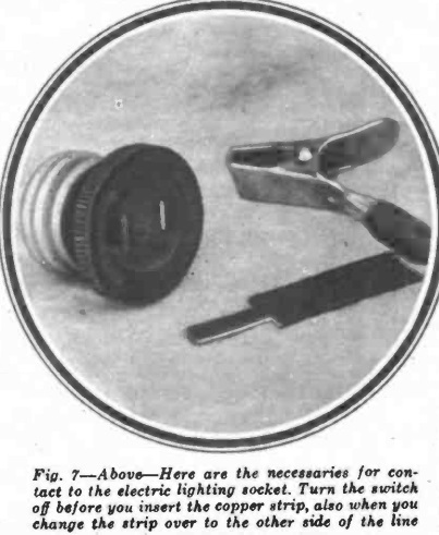
The set is small enough to be tucked away in a handbag, convenient to use, and ready for work at a second’s notice. In particular, he points out numerous available antennas. In the photo, he is using the wires of a fence as antenna and counterpoise, “even though the farmer didn’t dream of such a thing when he put them there.” For the hotel, he suggests the electric wires, the telephone, or even the button for calling the bellboy. He notes that the two capacitors on the antenna and ground leads mean that it won’t affect the phone. And (unless something goes wrong), they also make it possible to hook directly to the power wiring. (When inserting the copper strips in the outlet, he notes that the light should be turned off.)
He warns to be careful with the regeneration, and not let the set oscillate any longer than necessary. Not only will it distort the signal, but it will also disturb other nearby listeners.
May 22, 2026, was a sad day in radio broadcasting history, as the CBS Radio Network went dark after 99 years. The final top-of-the hour newscast was at 11:00 PM Eastern. For most of the day, it was business as usual at the network, as it carried national and world news. The last broadcast was a farewell message. You can listen to the 11:00 newscast at this link, The one-minute bulletin at the bottom of the hour was the very final broadcast, and is at this link.
The network produced this retrospective, which aired during the network’s final week:
One of the network’s oldest affiliates was WCCO in Minneapolis-St. Paul. For a time, it was owned by the network. The owned and operated stations were spun off as Audacy Inc., and those stations switched to the ABC network. (ABC is a relative newcomer, dating back to 1945 when it was spun off from the NBC Blue Network.)
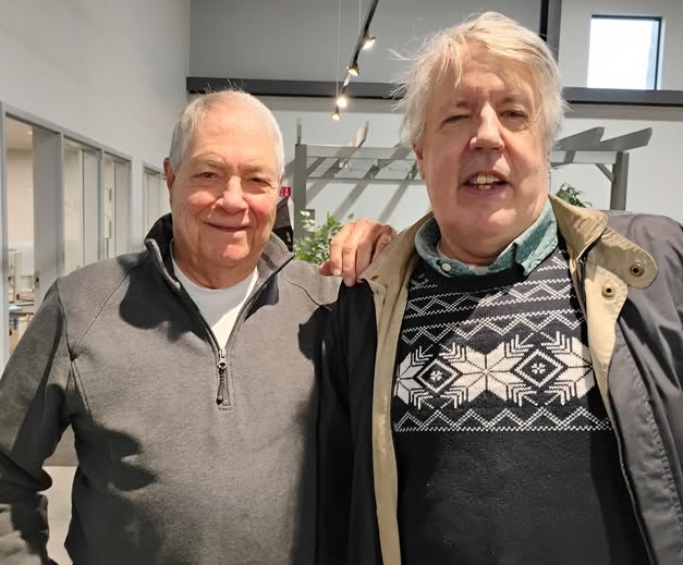
Coincidentally, one of the long-term WCCO staff members, Denny Long, who had served as announcer (and originally, music director) of WCCO, is retiring at the end of the month after 55 years at the station. As far as I know, he is the last employee of the station from the years when I grew up, when the station was a constant soundtrack for most homes in Minnesota. He did a remote broadcast today, and it was only fitting that this website, devoted as it is to radio history, paid him a visit and wished him the best. He is the handsome gentleman at the left, and you can hear some of his soundchecks covering over half a century at this link.
If you want to make the CBS sounder your phone’s ring tone, here it is:
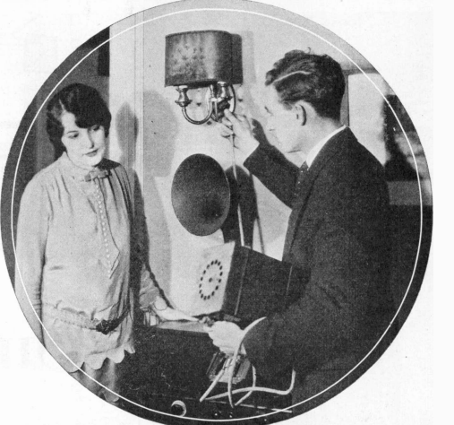
Shown here a hundred years ago is a service man from Dreher Radio Company, New York, or possibly the proprietor himself, Fred Dreher, shown in the May 1926 issue of Radio Retailing. Dreher had originally considered the service side of the business to be a necessity, but not necessarily a profit center. But after crunching the numbers, he came to the realization that, if done right, service could be a big profit center for the company. It wasn’t just the service itself. But when the customer was in the home, it was the perfect opportunity to sell accessories, such as batteries and tubes.
The key takeaway was that the service man, in order to make the endeavor profitable, had to see himself as a salesman of accessories, and not just a service man.
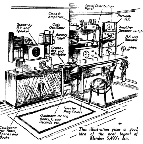
Eighty-five years ago this month, the May 1941 issue of Practical Wireless showed this efficient shortwave listening post of a listener in Sussex, England.
The SWL is identified only as Member number 5490 of the magazine’s listener’s club, perhaps since he was awaiting call-up at a telegraphist in the Royal Navy. The member notes that his normal receiving speed was 32 WPM, but he had managed to copy a few pages of French text at 42 WPM. He notes that he was able to copy 53 WPM, but only for one minute.
The main receiver was an Eddystone All World Two. The backup rig was homemade, and there was also a portable, which could be fed into a 2-1/2 watt amplifier. The gramophone pickup could be fed to the same amplifier. When reception was not good, he could feed the microphone or gramophone into the amplifier for some home broadcasting.
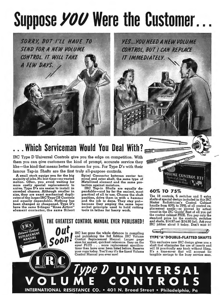 I don’t envy the poor radio serviceman shown in the left illustration, in the June 1941 issue of Radio Retailing. That customer doesn’t look very happy. If the poor guy got drafted the next year, the drill sergeant couldn’t scare him any more than she did. She was going to miss her favorite programs for a few days, and it looks like she’s taking her wrath out on him.