Monthly Archives: April 2016

Chiyono “Suzy” Cugita Suzuki, J1DN, J2IX

1936AprRadioNews

Shown here in the April 1936 issue of Radio News is Miss Chiyono “Suzy” Cugita, then J1DN, and later, after her marriage and 1937 move to Tokyo, Chiyono Suzuki, J2IX. Five years before Pearl Harbor, she was doing her best to promote international good will on the ham bands. She was active on both phone and CW, and served as the foreign QSL manager for JARL.

The magazine notes that she was Japan’s only YL operator, and had contacted more than a hundred U.S. hams, as well as Australia, South America, and Siberia.

Her QSL and more photos can be found at HamGallery.com.

Click Here For Today’s Ripley’s Believe It Or Not Cartoon


Ansley Paneltone Built-In Shortwave Receiver

1946AprilPM

In 1946, the war was over, and it was time to start designing the dream house.  A dream house wouldn’t be complete without a built-in radio.  And if you’re going to build a radio into your house, it may as well be a shortwave radio!

Shown here in the April 1946 issue of Popular Mechanics is just that.  It is the Ansley Paneltone receiver.  With one of these babies, you would have a 17 tube radio behind the wall. In addition to the standard broadcast band,it would cover both FM and shortwave, with pushbutton tuning. There was also provision for a phonograph connection. The 12 inch speaker would put out 15 watts of room filling audio.

I haven’t been able to find any evidence that this set ever made it into production. I have found references to the smaller 7 tube set shown in the same article, which covered just the standard broadcast band. It too featured pushbutton tuning, and its six inch speaker put out five watts.  You can find more information about that set, which also carried the Ansley Paneltone name, at RadioMuseum.org.


Click Here For Today’s Ripley’s Believe It Or Not Cartoon


1956 Worm Farming!

1956AprilBL

Sixty years ago this month, the April 1956 issue of Boys’ Life showed entrepreneurial scouts how to go into business for themselves, with practically zero capital investment, by taking advantage of the fortune crawling under their feet:  By starting their own worm farm.

The magazine explained the whole business from start to marketing their wares.  The initial investment was practically zero, since the entire breeding stock could be harvested from the back yard.

Boys could expect to get about 35 cents per five dozen by packaging them in containers available for about one cent, and the magazine explained the best sources for the containers. The best market was suggested to be sporting goods stores and bait and tackle shops. It advised boys to “call on all the stores you can reach and begin to establish a trade. Let them know that you can supply all the worms they need on short notice so they won’t have to stock a large supply at any one time.” The article suggested that it might be necessary to leave them on consignment. Later on, they could expand to neighboring towns, and even advertise nationally, with a suggested price of about $4 per thousand.

“It takes time to build up a constant source of orders, but since the worms are doing most of the work at no cost to you there is no labor problem or upkeep to worry about.”

Click Here For Today’s Ripley’s Believe It Or Not Cartoon


1941 Motorola Bike Radio

1941Apr27RadioGuideThis ad appeared 75 years ago today in Radio Guide magazine, April 26, 1941.  I suspect a lot of boys drooled over the prospect of having a radio on their bike.  For details on how to “win” one “free,” they were to write to the Boy Sales Manager of the magazine.  Undoubtedly, they would be told how many subscriptions they would need to sell to win the radio.  I suspect they would have to sell quite a few.  The magazine had a single issue price of ten cents, and an annual subscription was $4.  The radio itself appears to be the Motorola model B-150, with a retail price of $19.95.

The radio was probably a fairly good performer, being a three-tube superhet. Its tube lineup consisted of a 1A7GT, 3A8GT, and 1Q5GT, and had a 4 inch speaker. More information is available at RadioMuseum.org.

The set was powered by a combination A-B battery from Ray-O-Vac, which mounted on the frame of the bicycle. It also featured a whip antenna.  One novel feature of the set is that it had permeability tuning, meaning that the tuning knob adjusted the slug of an inductor, rather than moving a variable capacitor.

You can see a surviving example of the set at OldBike.eu.  Update:  Greg Farmer sent a link to a nice example of the radio at this link.  The radio, along with a bike of the same vintage, was on display at the Pavek Museum of Broadcasting in St. Louis Park, MN.

Click Here For Today’s Ripley’s Believe It Or Not Cartoon


1926 Metal Detector


1926AprRadioNewsNinety years ago this month, the April 1926 issue of Radio News showed this metal detector.

The magazine billed the device as one to prevent employee pilferage: “During the past few years, and especially since the war, it has been found necessary by the management of many large factories to maintain a close inspection of their employees when the latter pass from work; as otherwise the dishonest element, always found among them, would be certain to seize the opportunity to carry away tools and valuable small articles of manufacture, either completed or partially of manufacture, either completed or partially so.”

1926AprRadioNewsDiagTo solve the problem, this device served as a metal detector. Inside the gate was a coil, which was part of an audio oscillator. When metal passed through the coil, the permeability changed, which caused the frequency to change.

To detect small changes in frequency, this oscillator was paired up with another oscillator set to the same frequency. The signals were mixed, and the guard listened to the resulting beat in his headphones. A sudden change in the low frequency would alert him to an employee who would need to be searched more thoroughly.

1926AprRadioNewsPhotoThis system was apparently in use in at least one German factory, as shown in the photo here.

Click Here For Today’s Ripley’s Believe It Or Not Cartoon


1956 British “Transistorette”

1956AprRadioConstructor

It’s likely that many of the first transistor radios to show up in the British Isles were the “Transistorette,” built according to plans appearing in a four-part series of articles in Radio Constructor magazine. The April 1956 issue contained the third in the series, which completed the electronics of the set. The final article the next month provided details on constructing the cabinet for the portable set.

This issue covered most of the electrical wiring of the set, and included some precautions for those who were new to work with transistors. “Apart from the care which is normally needed when wiring up any miniaturized equipment, especial attention has to be paid in this case to the question of preventing damage to the transistors by overheating.”

The article cautioned to use sufficiently long leads on the transistors, and to install them last. In particular, it called for using “laid-on” joints for the transistors. Another piece of wire was used to the final connection. Then, the lead of the transistor was quickly tinned and laid against that conductor.  “A quick application of the soldering iron then causes the solder on the tag-spill to cover the lead-out wire and a quite satisfactory joint results. This joint should be just as good as that given by the more normal method of twisting the appropriate lead around its tag before soldering, and it has the considerable advantage of reducing any possible risk of overheating the transistor. It also enables transistors to be removed from the chassis in a similarly quick manner, should this ever be required.”

Click Here For Today’s Ripley’s Believe It Or Not Cartoon


Feed My Starving Children

FMSC
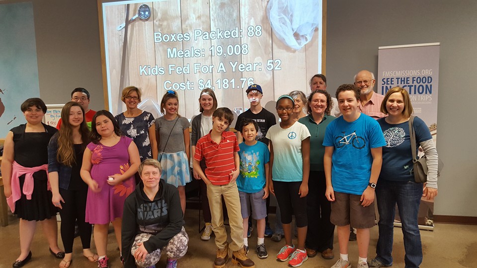
Today, my son and I, together with a group from our church, Christ Lutheran Church On Capitol Hill, spent a couple of hours packing meals at Feed My Starving Children (FMSC), a Christian relief organization which prepackages meals for distribution to malnourished children distributed by partner organizations around the world.  We were at the facility in Eagan, Minnesota, and the organization has similar facilities in Minnesota, Illinois, and Arizona.

The meals we packed consisted of roughly equal quantities of rice and soy, along with dehydrated vegetables and a “vitamin” component which is essentially dehydrated chicken broth.  It’s designed to be a palatable and nutritious food source.  We were given a small sample at the end of our shift, and it is quite good, although it understandably has a bit of a “dehydrated” taste to it.

FMSC also provides other similar packaged food suitable for infants and small children.

Volunteers are usually told exactly where the fruits of their labor are going to be sent, but in this case, FMSC had the good problem of having an excess of product at the moment.  But we were told that the most likely countries to receive our shipment would be Haiti, Nicaragua, or the Philippines.  We were told that our food would probably be in the hands of the intended recipients in July.

While FMSC is not primarily a disaster relief agency, since Typhoon Haiyan in the Philippines in 2013, they have been involved in disaster relief, they have a readily available supply of suitable food available.  After Haiyan, FMSC food was in the hands of refugees within 48 hours, and many of them had only this food to eat for a month as they concentrated on rebuilding.

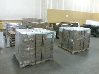
Today, there were about 80 volunteers from our church and from other churches and organizations.  We worked in a very efficient assembly line operation, in teams of about 10.  I spent most of my time scooping ingredients into the packages, while other volunteers got the packages ready, sealed them, boxed them, and put the boxes on pallets.  Shown above are two of the pallets we completed.  Each pallet contains 27 boxes, with 36 packages inside each box.  Each package provides six meals.  So the picture above shows enough to feed 5832 people for one meal.  We went through one bag of rice.  I glanced at the label, and it said 2000 pounds.

We were shown the photo of an emaciated infant, and then the photo taken only four months later of a healthy child.  We were also shown his picture taken a few years later, of a happy kid indistinguishable from any other kid you would see anywhere in the world.  When asked what he wants to be when he grows up, he says he wants to be the president of Haiti.

But it was pointed out to us that for millions of kids around the world, the question “what do you want to be when you grow up” is an alien concept.  They’re so worried about the next meal that it never even occurs to them to think about the future.

13087898_10153444105842623_2522056119384775107_n


Click Here For Today’s Ripley’s Believe It Or Not Cartoon


1966 FCC HELP Proposal

1966HeathCB

Fifty years ago, the FCC was considering a new radio service which never came to fruition. This was the Highway Emergency Locating Plan Radio Service (HELP), which was petitioned for by the Automobile Manufacturers Association, Inc. Described in the June 1965 issue of Popular Electronics, the plan called for two channels within the existing CB band, 27.235 and 27.245. For those familiar with 23 channel CB radios of the day, these were the mysterious channels 22A and 22B, which were included on the dial, but disabled.

HELP would be a new radio service, but would allow existing Class D CB operators to operate on thos channels for motorist assistance. The idea was the vehicles would be equipped with radios for these channels, for use in summoning help in an emergency. Land stations would be allowed 30 watts, with mobiles using 5 watts.

A March 1966 FCC order looked favorably on the proposal, and FCC staff was tasked with researching it further. However, it never came to fruition.

1966AvcommManufacturers were apparently eager to get on board with the HELP service. As mentioned above, most 23 channel CB radios included channels 22A and 22B. In the 1965 ad shown above, Heath advertises this 25 channel CB transceiver, including the 2 HELP channels. An asterisk next to the description of those channels points out that the FCC petition is still pending.

And shown here in the April 1966 issue of Radio TV Experimenter is a 200 milliwatt handheld, the Mark 1 HELP Transciver from the Avcomm Division of what the magazine calls “a company with the unlikely name of Ajax Floor Products Corp.”  The crystal controlled radio would operate on any frequency between 25-50 MHz.  The company promised coverage of up to a mile in tall buildings or heavy traffic areas, up to five miles line of sight, and 7 miles in open country or over water.  The receiver was a superhet, and the magazine opined that it looked “like a good bet to toss in the glove compartment if you want the reassurance of having a rig along with you on a trip without having to make a permanent installation.”

An interesting discussion of the HELP proposal can be found at RadioReference.com.


Click Here For Today’s Ripley’s Believe It Or Not Cartoon


1941 Popular Mechanics One Tube Receiver

1941AprilPM

Seventy-five years ago, this month’s issue of Popular Mechanics,
April 1941, carried the plans for this simple one-tube receiver, which covered the broadcast band, as well as the 160 and 80 meter bands.

Using a 1S4 Tube, the set required a B battery of only 6 volts, meaning that it could be run with four flashlight batteries in series. Another two flashlight batteries in parallel powered the filaments, and the total cost of batteries was only 30 cents.

Also presented was an audio amplifier on a separate chassis, also using a 1S4, which would drive a three inch speaker. Or, as the user in this drawing is shown, the set could be run by itself with headphones. Volume and regeneration were controlled by an adjustable tickler coil, keep the parts count of the set low.

1941AprilPMSchematic

Click Here For Today’s Ripley’s Believe It Or Not Cartoon


1941 Compact Portable Transmitter

1941AprilQSTSeventy-five years ago this month, the April 1941 issue of QST carried the plans for this simple one-tube CW transmitter for 80 and 40 meters.

The set was billed as a compact portable transmitter for field or emergency use, but could also function as the control stage of the home station until being put into place for field duty. According to the article, the total cost, including tube and cabinet, was less than $12.

The set required 6 volts for the filament, and 250 volts DC for the B+. This could be derived from batteries, and the article pointed out that this would be good for several hundred hours of intermittent operation. But it was really designed to run from the vibrator power supply of the car radio. The article advised builders to consult with the manufacturer of the car radio to get the wiring diagram, since those could vary considerably. But the car radio’s power supply would be expected to have a typical output of 200-250 volts at 50 mA. A single pole double throw switch could be added to the car radio to switch the power from the transmitter to the receiver.

The top of the set had three insulators. Two had connections that would be used with a doublet, and the third was to be used with a single wire antenna. The article noted that the transmitter could tune virtually any antenna.

1941AprilQST2

Click Here For Today’s Ripley’s Believe It Or Not Cartoon