Category Archives: Radio history

Another SOS by Flashlight, 1915

1915WirelessAgeSOS

The March 1915 issue of The Wireless Age carries the tale of the steamship Chester, a tanker owned by the American Petroleum Company. She had left New York on January 23 en route to Rotterdam with a cargo of oil. She ran into rough weather a few days out and suffered a tank bulkhead burst, but there was no immediate peril.

But on the afternoon of February 2, a giant wave swept over the vessel. The hatches were demolished and oil was pouring from the tanks. The engines were flooded and stopped; most of the contents of the deck, including the lifeboats were swept away; and the ship was listing so badly that the rails were in the water.

The ship was not equipped with wireless, but the second officer, Jacobus W. Waale, held a cargo grade wireless certificate and was familiar with Morse. With the one remaining signalling lamp and a flashlight, he began to signal SOS over the dark waves. All that night, no ship spotted the signal. The next day, signal flags were hoisted, also to no avail. When darkness once again fell, Waale once again resumed signalling with the lights.

Crew of the Chester aboard the Philadelphia after rescue.

Crew of the Chester aboard the Philadelphia after rescue.

Fortunately, the steamer Philadelphia was making its way from Liverpool to New York. Normally, she would have been on a more southerly route, but had moved closer to the Chester’s position in an effort to avoid storms. A tiny spark of the Chester’s light was spotted from the deck of the Philadelphia, and the officers finally realized that a ship was trying to signal them. One of the officers had some knowledge of Morse Code and made out that it was an SOS. The captain instructed the wireless operator J. Edward Jones to establish contact with the signalling ship. This, of course, was in vain, since the Chester was not equipped with wireless. The ship’s second wireless operator, William V. Moore, was summoned to the deck to make contact with the signal light.

He flashed the message, “what is the matter?” It took almost thirty minutes to receive the reply, “we are a wreck.” The Philadelphia inquired as to whether the distressed ship had any boats, to which it received a negative reply. When asked “do you want to be taken off,” the Chester replied “yes.” The rescue was not easy, but it was facilitated by the use of the lights.

The Chester, as seen from the Philadelphia after the rescue.

The Chester, as seen from the Philadelphia after the rescue.

Interestingly, this incident came just a few months after another notable incident involving a flashlight used to send SOS from the Hanalei recounted in an earlier post.


1957 CONELRAD The Easy Way

1957ConelradStarting in 1957, U.S. Amateur Radio operators were required to participate in CONELRAD. (If you’re unfamiliar with CONELRAD, I explain it in other posts, including this one.) Under the regulations that took effect that year, hams were required to monitor an AM broadcast station whenever transmitting. If that station went off the air, the ham was required to check to see if the absence from the air was due to a CONELRAD alert. If so, he was required to leave the air.

The regulations could be satisfied by keeping an AM radio on low volume in the background, but the preferred method was to have an automated alarm that would sound if an AM station left the air. One popular receiver for that purpose was the Heathkit CA-1 CONELRAD alarm, which was an external monitor that would be hooked to a receiver. Other dedicated receivers wwere available, such as the Kaar Engineering Conalert II, although a unit such as that would be out of the price range of most hams, and probably used mostly by broadcast stations.

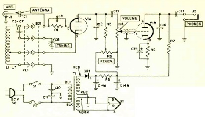
The April, 1957, issue of Radio News carries an article entitled “Conelrad the Easy Way,” with a simple method of converting a five-tube broadcast receiver into a CONELRAD monitor. As shown in the schematic above, it required only three parts, and allowed the radio to be used for normal listening. The additions to the circuit are the three parts inside the dotted lines.

This circuit ties in to the AVC voltage of the first audio amplifier. As long as there is an AVC voltage present, the added resistor biases the first tube to silence the radio. But if the AVC voltage disappears (because there is no signal present), then the output of the final audio amplifier gets fed back to the first audio amplifier, causing the two stages to break into oscillation to emit a loud squeal.

It’s a pretty ingenious and easy modification, and the author reports that many hams were using it and that he thought “it is the answer to the Conelrad needs of most hams.” He even notes that the circuit “is so simple that many broadcast listeners may want to install it on their receivers, just in case.”

The author, by the way, is John T. Frye, W9EGV. If that name rings a bell, it is because Frye was a prolific writer in many electronics and radio magazines. He was most famous as the author of the “Carl and Jerry” stories that appeared in Popular Electronics from 1954-1964.


More Radio on the Beach, 1924

1924RadioJournalHere, in the June-July 1924 issue of Radio Journal is another radio whose owners decided to take it to the beach. The radio is a Kodel portable, the beach is Far Rockaway, Queens, New York, and the owners are Lois Wilde and Stella Wooten of the Ziegfeld Follies.  Miss Wilde went on to become leading lady in a number of 1930’s Westerns, before being injured in an automobile accident in 1938.


Integrated Circuits Fifty Years Ago

EI1965IC

Fifty years ago this month, the cover of the March 1965 issue of Electronics Illustrated showed this integrated circuit, the Motorola MC556G. The case of this IC measured 5/16 inch in diameter, and the chip itself measured about 1/10 inch square. It contained six transistors and eight resistors. The accompanying article noted that it was now on the market at a price that hobbyists could afford to use for experimental projects,  $3.35.

To put the new device in perspective, the article compared it to the still ubiquitous 5-tube radio, which consisted of about six basic circuits using about 20-30 components. The article noted that the day would soon arrive when one or two IC’s would constitute a “complete radio that is equivalent in performance to that five-tube AC/DC job.”  That prediction came true only seven years later, in 1972 with the ZN414 AM radio IC from GEC-Plessey. The modern functional equivalent of that IC is the MK484/TA7642 am-Radio IC, which is a complete radio in a chip, requiring as its only external components a battery, coil, tuning capacitor, and earphone.

While the eight transistors in a 1/10 inch package was revolutionary at the time, transistors in current IC’s are in the range of tens of nanometers in size, allowing several billion transistors per chip. But building something with an IC was revolutionary fifty years ago, and Electronics Illustrated featured two projects making use of the MC356G. The first was a square-wave signal generator, and the second was the AM radio shown below. In this diagram, the portion shown in black is internal to the IC, and the components shown in red are external. As you can see, the circuit makes use of four of the chip’s eight transistors, and four of its resistors.

1965ICradioschematic

The IC was designed for use as a logic gate, but transistors are transistors, and they could be used for their amplification function. For the radio in particular, getting the circuit to work took several experimental designs, but the author finally “hit upon one that has a decent amount of sensitivity, selectivity, and audio output.” The author noted that most of the headaches in designing the radio were caused by the close proximity of the components on the chip. Having only 1/10 of an inch to work1965ICradio with presented leakage paths between the circuits that would be out of the ordinary for a radio designer.  The finished project is shown here.

In the design, two of the transistors are used as RF amplifiers, with the signal being fed back through a regeneration control. The second of those transistors also amplifies the audio, and there are two more audio amplifier stages. The actual detector consists of two external diodes.

Click Here For Today’s Ripley’s Believe It Or Not Cartoon


Minnesota Wireless Association in 1915

MNWirelessAssn1915

MplsCityHall

Minneapolis City Hall 2012 cropped” by Jason Riedy from East Point, GA, USA. Licensed under CC BY 2.0 via Wikimedia Commons.

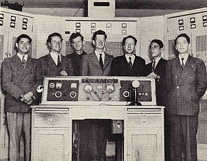
The Minnesota Wireless Association (MWA), according to its QRZ.com listing, has been in existence since 1914, and that fact is borne out by the photograph above, which appeared a hundred years ago, in the March 1915 issue of Popular Mechanics.  The article describes the station installed in the Minneapolis City Hall, a structure which is still in existence and easily recognizable, as seen in the modern photo here.

The magazine reported that the station had just been installed by the Minnesota Wireless Association, and was “probably the largest private wireless station” at the time. It noted that the instruments in the station were “arranged with particular reference to experimental work, which will include tests and comparisons of new apparatus, studies of stray electrical disturbances, and the development of new apparatus.” The antenna consisted of eleven wires between the two towers, 400 feet above ground at the clock tower.

The article reported a receiving range of 4000 miles and a “sending range limited only by the power used.” The station had a license to operate on any wavelength and with any power, but the article noted that “every precaution will be taken not to interfere with other stations.” The station apparently used only radiotelegraph at the time, but the article noted that a wireless telephone set was under construction.

According to a 1914 Wireless Age account, the station’s best DX was Colon, Panama, as member Claud Sweeny had copied that signal.  The club also reported that the station had excellent reception of time signals, presumably from NAA in Arlington, Virginia, and it was likely that those signals would be utilized for controlling the city clock, “thus giving Minneapolis the first radio municipal time.”

The MWA currently holds the call sign W0AA, although I’m not sure when they received this call.  According to the Club’s QRZ.com listing, they’ve held it since 1967, in memory of one of its members, Art Andersen, who had held the call prior to his death.  However, W0AA is shown in the 1952 call book as belonging to the club, with Andersen listed as the trustee.  The 1938 call book shows W9AA as belonging to a ham in Chicago, so it appears that the club got the ‘AA call sometime between 1938 and 1952.

According to the September 1914 issue of Wireless Age, the station bore the call sign 9ZE.  That call is listed in the 1914 call book as being held by Philip E. Edelman, who is identified in the Wireless Age article as being the Association’s president.   The club is listed in the 1920 call book as holding the license for special land station 9ZT, with an address of 402 Courthouse Bldg.  In the 1926 call book, the licensee for that call sign is a familiar name in Amateur Radio history, D.C. Wallace, later W6AM.  A QST search for 9ZT reveals that the call was Wallace’s personal call sign until he moved to California in the 1920’s.  It’s unclear, therefore, whether MWA has continously held a license for the last hundred years.  But as the photo above proves, they have been a force in Amateur Radio for a century, as 9ZE, 9ZT, W0AA, and possibly other call signs.

Read More At Amazon

Don C. Wallace: W6AM, Amateur Radio’s Pioneer


Click Here For Today’s Ripley’s Believe It Or Not Cartoon


Morse Code Secret Message in Colombian Song

FARC Guerillas. Wikipedia photo.

FARC Guerillas. Wikipedia photo.

Morse Code was used in 2010 to get a secret message to hostages being held in the Colombian jungle by FARC guerrillas.  Some of the hostages had been held for years, and the Colombian army wanted to deliver a message that they hadn’t been forgotten, that some hostages had already been rescued, and that they were next.

Since it was known that some of the prisoners knew Morse Code, and the captors probably didn’t, the Army decided to insert a Morse message into a popular song and get it broadcast on the air.  The result was the song heard on this YouTube video, Mejores Dias (Better Days), recorded by Colombian studio musicians Natalia Gutierrez Y Angelo.

I knew there was Morse Code coming, and I heard it the first time.  If I hadn’t been expecting it, I suspect it might have taken a couple of plays for me to notice.  And once I knew it was there, it took me several times to get the entire message, since it is well hidden in the music.  But if I had a lot of time on my hands, I would eventually decode the entire message.  It’s in the chorus, starting at about 1:30, 2:30, and 3:40 in the video, following the words, “escuchas esta mensaje, hermano” (listen to this message, brother).

To make sure that the song was heard, the Colombian army arranged to have it inserted into the play lists of the government-owned stations serving the jungle areas where the hostages were being held.  The guerrillas listened to the radio, and the hostages later reported that they even liked the song.  The message was heard, as rescued hostages later reported.

The message reads:   “19 LIBERADOS. SIGUEN USTEDES. ANIMO.”  (19 PEOPLE RESCUED. YOU’RE NEXT. DON’T LOSE HOPE.)  Even if you have only a passing knowledge of Morse Code, you will hear it, and you’ll eventually be able to decode it.

More information is available at TheVerge.com, at the article linked below.

References


Heathkit GR-64, 1965

HeathGR64We recently looked at the Knight-Kit Star Roamer Receiver from 1964. It was a beginner’s general coverage receiver and was quite popular. The February 1965 issue of Popular Electronics announces another popular general coverage receiver for beginning SWL’s and hams, the Heathkit GR-64 shown here. It covered 550 kHz through 30 MHz in four bands, and made do with four tubes, a mixer-amplifier, IF amplifier, detector-audio amplifier, and audio output. The power rectifier consisted of two silicon diodes.

The kit retailed for $39.95.  The assembly manual is available for download at this link.


The Luxembourg Effect

LuxembourgEffect

An interesting ionospheric effect was first noticed about 80 years ago, and reported 80 years ago this month in Radio Craft magazine, February 1935.  Radio Luxembourg operated on 252 kHz, with a powerful 150 kw signal designed to provide coverage in England.

The phenomenon was discovered in 1933 by B.D.H. Tellegen, in Eindhoven, Netherlands, who was listening to a station in Beromunster, Switzerland, on 652 kHz. In the background of the Swiss signal, he could hear the audio of Radio Luxembourg. This same phenomenon was reported by other listeners. Due to the distance between the three points involved, it could not be explained by the receiver being overloaded. The Luxembourg signal could be heard only when the Swiss station was transmitting.

Tellegen noted that the three points were in a straight line: When the signal from the Swiss station made its way to the Netherlands, it passed directly over Luxembourg. He correctly theorized that the carrier of the Swiss station’s signal was being modulated in the ionosphere as it passed through the strong signal of Radio Luxembourg in the ionosphere.

The ionosphere had only recently been discovered, and was not totally understood. It was previously supposed that the ionosphere was a linear medium, through which radio waves passively reflected. But the existence of the Luxembourg Effect showed that the ionosphere could be artificially “heated,” to produce non-linear effects.

Interestingly, the carrier frequency of the signal didn’t seem to be critical.  The modulation of the interfering signal was superimposed on the other signal without regard to the carrier frequency.  Subsequent research showed that most of the effect took place in the lower range of the audio frequencies.

Much to the dismay of conspiracy theorists, this is the phenomenon that the High Frequency Active Auroral Research Program (HAARP) was working with. It’s relatively easy to generate a strong radio signal in the High Frequency (HF) region. HAARP had transmitters that could generate 3.6 MW signals from 2.8-10 MHz and radiate them toward the ionosphere. This strong signal was able to generate the same kind of “heating” effects caused by Radio Luxembourg.

It’s more difficult to generate signals in the Extremely Low Frequency (ELF) region. Among other things, ELF signals are used to communicate with submarines. The main idea of HAARP was to generate these signals not in a transmitter, but in the ionosphere itself, by mixing two strong HF signals. For example, it would be practically impossible to generate a radio wave of 0.1 Hz with a transmitter. But by beaming two signals into the ionosphere, one at 4.000000 MHz, and one at 4.0000001 MHz, the result would be a radio wave, generated in the ionosphere, with a frequency of the difference, 0.0000001 MHz, or 0.1 Hz.

The phenomenon is sometimes called the Luxembourg-Gorky effect, since the powerful longwave transmitter at Gorky, USSR, produced similar effects.

References


One-Tube Wartime Receiver, 1945

RadioCraftFeb45

Radio parts were in short supply during the War, and radio enthusiasts had to make do with what they had. “H.T.,” a resident of Bothell, Washington, apparently had in his junk box a 1D8GT tube, and a low-impedance earphone, and wanted to know what he could do with them. So he wrote to the editors of Radio Craft magazine asking for a diagram of a receiver covering the broadcast band making use of the parts he had. He wanted to mount the earphone in the cabinet for use as a small speaker.

The editors indulged him and provided this diagram in the February 1945 issue. It was reprinted from the July 1940 issue, and showed how the combination diode-triode-pentode tube could be used in this circuit. The triode section of the tube was an RF amplifier, followed by the diode detector, with the pentode serving as an audio amplifier. Unfortunately for H.T., the low impedance earphone would need to be used in conjunction with an audio transformer. This set would drive a pair of high-impedance headphones, but to use it with his low-impedance earphone, it would need to be wired as shown for the speaker. So H.T. had to find himself either a set of hi-z headphones, or the output transformer, in addition to what he already owned.

The other hard-to-obtain part would be the variable capacitor. The circuit here shows a ganged condenser, but the response pointed out that two separate condensers would provide better results.

Click Here For Today’s Ripley’s Believe It Or Not Cartoon


1940 Two-Tube Two-Band Receiver

1940FebPM75 years ago, Popular Mechanics, February 1940, carried the plans for this simple two-tube, two-band receiver, which could be run off flashlight batteries, 8 for the B+, and one for the filaments. It used two Type 49 tubes, and tuned both the broadcast band and short wave. The short wave band covered the then-police freuencies, as well as the 160 and 80 meter ham bands. It was mounted on a wooden chassis and had a wooden front panel.  It was a very simple design, with one tube serving as the regenerative detector, and the second as audio amplifier.

This particular receiver would be difficult to duplicate, since the coils are unobtanium. The article notes that the coil is a “three-circuit tuner” which did away with “tedious coil winding, often a stumbling block for beginners.” The coil came with a pre-marked terminal strip which made wiring errors next to impossible. The rotating tickler coil was included. It even had a built-in switch wired to the taps on the coil for easy switching from broadcast to short wave.

As was often the case, the Popular Mechanics project was available in kit form from Allied Radio. The 1941 catalog shows this kit as selling for $4.70, plus $1.39 for the tubes and batteries.

Click Here For Today’s Ripley’s Believe It Or Not Cartoon