Category Archives: Radio history

Heathkit CB-1

1959Sep59PE2We’ve previously written (here and here) about the Heathkit Model CB-1 CB transceiver. Sixty years ago this month, the September 1959 issue of Popular Electronics carried a review of the kit.

The magazine described the set as handsome and lightweight and convenient for use either at home or in the car. The set had a built-in 120 volt power supply, and could be used mobile with a vibrator power supply.

The set was easy to put together, but the magazine warned not to rush and try to do it in a single evening. During that sunspot peak, the author reported that stations from several time zones were heard. When operated from the car, a station a few miles away reported a good signal with high modulation.


1944 British One Tube Regen

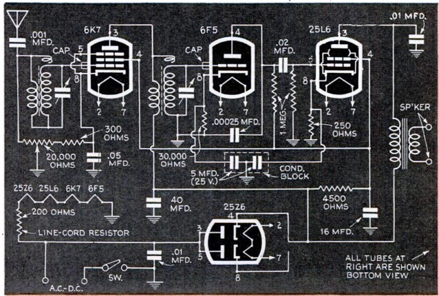
1944SeptPractWireless75 years ago this month, the September 1944 issue of the British publication Practical Wireless carried the plans for this very basic wartime one-tube regenerative receiver. The set employed a 1D8GT dual tube, half of which served as detector, with the other half serving as AF amp, providing about 100 mW of audio to the speaker. With a ten-foot antenna, the set would easily pull in the BBC home, European, and armed forces services.

1944SeptPractWirelessSchematic


1969 AM-FM Portables

1969SepEI3Fifty years ago this month, the September 1969 issue of Electronics Illustrated reviewed a number of pocket (for large pockets, that is) portable AM-FM receivers.

The magazine noted that many such sets were showing up as loss leaders and prices below $10, and the article asked how these cheap models compared with more expensive brand names. The surprising result was that the cheap no-name sets performed as well as the more expensive models, although the more expensive sets were, in some cases, easier to tune and looked better. But the moral of the story was that these were a class of products where shopping strictly for price was the best strategy.


An Old Soviet Tube

1929RadioL

I’m not sure what this old tube is doing, but it appears on the cover of the September 1929 issue of the Soviet publication Радиолюбитель (Radio Amateur). One would think that the word written on the ground would add some context.  But according to Google translate, “скатертъюборога” means “tablecloth,” so that doesn’t seem to help.

Since I can’t think of any other reason why atheist Soviets would be showing Christian crosses, I assume that these are grave markers.  Modern Soviet tubes have replaced the old models, and this old tube is visiting his fallen comrades at the cemetery.  Perhaps he plans to have a picnic on the tablecloth.


1959 Radio/Intercom

1959RadioTVExp3Sixty years ago, the occasional publication Radio-TV Experimenter carried this interesting project. As the enclosure, it used an already antique crank-type wall telephone as the housing for a radio receiver, but put the telephone back into service as a home intercom.

According to the magazine, the phone was rapidly vanishing from the American scene, and interior decorators had been busy snatching them up to convert into spice cabinets, pin-up lamps, and liqueur chests. Instead, the magazine showed how to preserve the original communication function by providing an intercom between floors of a house, between house and garage, etc.

The radio function was added by use of something found in almost every home, “a small table-model radio set of the ac-dc type that has been set aside because of a broken cabinet, missing knob, or a minor circuit defect.” Such a radio was squeezed in, with the controls mounted under the phone’s writing desk.

Obtaining the phone was a matter of ordering one from Telephone Repair & Supply Co. of 1760 W. Lunt Ave., Chicago, where it was available for $7 plus postage for the 20 pound instrument. Most such surplus phones came with the crank, but not the magneto, since apparently the phone companies still needed some of those for their rural customers.  The phone will have been in service for fifty years, so the article gave details on how to refinish the wood and metal components.

The article next explained how to wire the phone back up. Even without the magneto, the ringer could be made to work by including a button on the side of the phone (where the crank used to be), wired to the bell through an induction coil. Presumably, the phone would ding once when the button was depressed. A three wire circuit (or two wires plus ground) was used to hook the phones together, with one wire for the voice connection and one for the ringer. The wiring diagram is shown here:

1959RadioTVExp4


1959 One Tube VHF Receiver

1959RadioTVExpSixty years ago, a 1959 issue of Radio-TV Experimenter carried the plans for this one-tube VHF receiver. The superregenerative set covered 27-200 MHz. Since the sunspot cycle was cooperative in 1959, the set pulled in a lot of DX. On the 10 meter amateur band, the author reported hearing hams in Mexico, Cuba, Alaska, and Japan. In addition, he pulled in paging services in California and Puerto Rico, and police stations in South America, all with an indoor wire antenna. With an outdoor beam antenna, he pulled in the audio of BBC television in London.

One half of the 12AT7 tube acted as the sensitive detector, with the other half serving as audio amplifier. Plug-in coils were used for band switching.

1959RadioTVExp2


1919 Portable Crystal Set

1919SeptRadioAmateurNews1919SeptRadioAmateurNews2A hundred years ago this month, the September 1919 issue of Radio Amateur News carried this “pocket size” (for large pockets, presumably) crystal set. According to the author, the set was, from Illinois with a 140 foot antenna, able to pull in NAA Arlington, NAR Key West, as well as a large number of ships off the Atlantic coast. Tuning was accomplished through taps on both the primary and secondary coils, and could tune to a maximum wavelength of 3500 meters (86 kHz).

The radio was mounted in a leather-covered carrying case for a No. 2 Folding Brownie Camera.  It was set so that one side could be opened completely, allowing access to controls. The detector was a galena crystal, and the set contained a test buzzer for use in finding the “sweet spot” on the crystal. A fixed capacitor was made of two 2×6 inch sheets of tinfoil, separated by wax paper and folded.


Science Fair Project: Hot Wire Ammeter

1969AugSepRadioTVExpThe young scientist looking for an award-winning science fair project can’t go wrong with this ammeter from the August-September 1969 issue of Radio-TV Experimenter.

The instrument can be constructed with materials from the hardware store, but will do accurate measurements of current, whether it is DC, AC, or even RF. It is a hot-wire ammeter, and was frequently used in the early days of radio for measuring RF current in order to calculate power. As the name implies, the current is measured by the expansion and contraction of a steel wire. As the current flows, the wire heats up. It is attached to a spring-loaded second wire, and that wire moves a pointer. A standard ammeter can be used to calibrate the device once constructed. In the photo here, the meter is shown measuring current from a dry cell battery (and a modern alkaline D cell will work just as well as the old-fashioned battery, especially when used with a battery holder). However, the instrument can also be used to measure AC current, and can be used as part of an experiment measuring current consumption of various kinds of light bulbs.


1969 Greeting Card Radio

1969SeptEICoverFifty years ago, the September 1969 issue of Electronics Illustrated showed how to put together this greeting card radio. The chasis was a 6×9 inch greeting card. On the left side is a homemade circuit board consisting of aluminum foil attached to cardboard with rubber cement. The top half of the circuit board is also the stator of the variable capacitor, with the rotor being another piece of foil cemented to cardboard. The crystal earphone was permanently attached, presumably meaning that extra postage was required.

If the idea looks familiar, it’s because we’ve featured similar ideas in the past, such as this 1947 one-tube set or this 1940 postcard radio.  If you’re looking for parts, see our crystal set parts page.

1969SepEI2


160 Meters in 1949

1949SepRadioElecThe 160 Meter band was reopened to use by Amateur Radio Operators in 1949, but the band was also used for the LORAN radio navigation system. That system allowed ships to plot their location quite accurately. It relied on shore stations that transmitted synchronized signals. The time difference between the two signals placed the ship on a given line, and by noting the intersection of two such lines, the location could be determined.

Because the band was shared, hams were limited in both frequency and power to protect the LORAN signals. The map shown above showed the initial restrictions in 1949, and appeared in the September 1949 issue of Radio Electronics.

Essentially, each state and territory was assigned two 25 kHz segments with specified day and night power levels. The Gulf Coast states were allowed 200 watts power during the day, but this segment of the country was not allowed on the air at all after local sunset.

By the mid-1970s when I got on the air, the restrictions had been relaxed considerably, and the band was quite good for regional contacts at night. While ‘phone operation was allowed, almost all of the activity I remember was CW. The restrictions as of 1975 are shown here, from the 1975 edition of the ARRL License Manual:

1975LicenseManual