Category Archives: Radio history

1939 Philco Radios

1939Sep13MilJour

This ad showing Philco’s line of radios appeared 80 years ago today in the September 13, 1939, issue of the Milwaukee Journal. From most browsers, you can view a full size copy by clicking twice on the image.


Women’s Royal Canadian Naval Service

1944SepManitobaCallingShown here, in the September 1944 issue of Manitoba Calling, the program guide of CKY Winnipeg, are two “Wrens” of the Women’s Royal Canadian Naval Service. Stationed atop the signal tower over Halifax harbor, these women did the job of Naval signalmen in visual signal work. They flashed and received messages to and from ships and relayed them to the Navy shore offices. The magazine noted that the tools of their trade were projection lamps, signal flags, binoculars, telescopes, telephone, and radio telephones.

The magazine noted that while nothing could compensate for the horror and destruction of war, there were some good results. One of those was the fact that women had been given the opportunity to serve Canada in a variety of jobs with few openings in peace time.

For another look at visual signalling methods, see our earlier post.


1934 HCJB QSL

1934HCJBqsl

Clarence Jones. Call of the Andes blog.

Clarence Jones. Call of the Andes blog.

We’ve previously shared the history of HCJB,

the missionary radio station in Quito, Ecuador. We noted that the station had its real start as a force on the shortwave bands in 1940, when it signed on with its new 10 kW transmitter. But as we noted, the staton really started in 1931 by American missionary Clarence W. Jones with a 200 watt transmitter in his own residence to a wire antenna.


1934JBLHindsThis early QSL card from the station confirms reception of a program on February 7, 1934. The card notes that the station was then on 73 meters running 150 watts. The card bears Jones’ signature, and the illustration suggests that the station was still in his residence and using a wire antenna. The card was addressed to J.B.L. Hinds of New York, shown in the illustration at left. He presumably pulled in the 150 watt signal with the set shown here. Hinds was the editor of the “Foreign Station Department” of Short Wave Radio magazine, and the card and this illustration appeared in the magazine’s September 1934 issue.

The listing of shortwave stations in the same magazine lists HCJB at 73.0 meters, 4.11 MHz.


1944 Meterless VTVM

1944SepServiceDuring the war, meter movements were extremely hard to come by, but a radio serviceman in need of an accurate measuring device could probably scrounge up a magic eye tube. This circuit on the cover of the September 1944 issue of Service magazine showed how to construct a very accurate vacuum tube voltmeter (VTVM) that didn’t actually require a meter. The switch was used to set the range, which could vary from 0-0.5 volts to 0-500 volts. Then, the 770 ohm potentiometer was adjusted to the point where the magic eye tube closed. The potentiometer was calibrated with the voltage, and the reading was obtained from that scale.

The magazine noted that the instrument was particularly good for tracking down transient or intermittent voltages that might not be seen because of the inertia of a standard meter movement. It noted that the instrument’s function was similar in many respects to an oscilloscope.


1919 Florida Keys Hurricane

This week marks the 100th anniversary of the 1919 Florida Keys Hurricane, which also had a major impact in Louisiana and Texas, in addition to the Caribbean. On September 7, 1919, the storm strengthened to hurricane intensity over the Bahamas, and continued to grow as it zeroed in on Key West. It ultimately strengthened to category 4 before making landfall at Dry Tortugas. The storm was the second strongest since 1851, and the ninth deadliest in U.S. history, with 772 fatalities.

Outside of the Keys, the state of Florida was relatively unscathed, although communications south of Miami was cut off. After the storm crossed into the Gulf, there was a false rumor that it had turned toward Louisiana. This caused warnings to be taken down for Corpus Christi, Texas, the day before landfall. Although the warning was re-instituted, the city was unprepared for the storm surge as high as 16 feet.

Among the dead were 310 in Texas, as well as 488 persons aboard a steamer found sunk between Key West and the Dry Tortugas. One of the survivors of the storm was a six year old Robert Simpson, who did have one family member perish in the storm. He went on to become a meteorologist and along with Herbert Saffir devised the Saffir-Simpson Hurricane Scale.

1919DecQSTAmateur Radio was still off the air, since restrictions on transmitting were not removed until October 1, 1919. Receiving, however, had been allowed since April 15, and Houston amateur radio operator Clifford W. Vick became a bit of a celebrity in his hometown by copying radio traffic related to the storm and passing these dispatches on to the local newspapers. The clipping at left appeared in QST in December 19, and notes that Vick made the point to the Houston papers that he could have done more good if the transmitting restrictions had been lifted.

Corpus Christi after the storm. Wikipedia photo.


The Holy Grail: Loudspeaker Volume with No External Antenna

1959Sep59

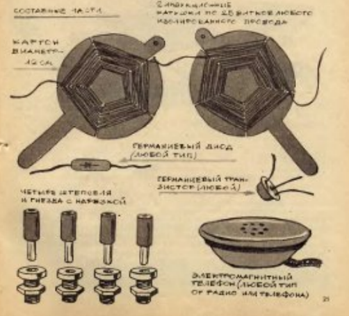
Sixty years ago this month, the September 1959 issue of Popular Electronics carried the plans for this three-transistor pocket transistor receiver with built-in antenna and speaker. It also pointed out the Holy Grail for the experimenter, and there’s more than a little bit of truth:

It is every hobbyist’s ambition one day to achieve loudspeaker operation using a single transistor and no external antenna.

The article noted that such a day was not here yet, but this three-transistor model was getting close. The internal loopstick antenna went to one stage of regenerative RF amplification, a diode served as detector, and two transistors provided loudspeaker volume.


1939 Electronic Project Lab

1939SepPSThe lucky young man shown here, now about 90 years old, is putting the finishing touches on an electronic project, courtesy of his miniature radio laboratory kit, as shown in the September 1939 issue of Popular Science.

The kit was packed compactly in a cardboard box with full instructions for making a radio receiver, a code practice set, a relay for turning on and off lights, and other projects. Included in the set was a soldering iron and spool of solder, allowing the set to teach a skill that “every amateur radio fan should learn to use.”

While such kits were arguably a lot cooler in 1939 when they came with a soldering iron and tubes, many such electronic project kits are still available, as shown by these Amazon links.  (These are affiliate links, meaning that this site gets a small commission if you buy after clicking on them.)


1939 3 Tube Portable

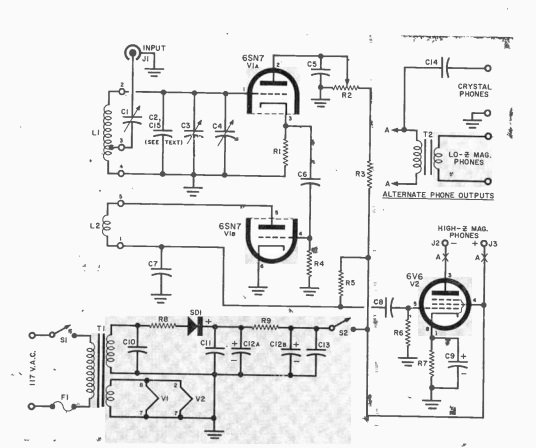
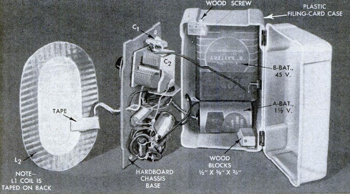
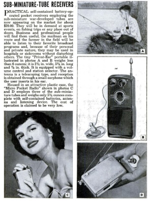
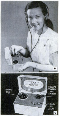
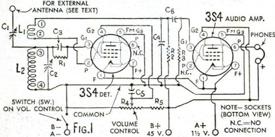
1939AugPS21939AugPS3This trio are enjoying a radio program out on the terrace thanks to a miniature portable receiver described in the August 1939 issue of Popular Science. The three-tube set drove a loudspeaker thanks to three miniature 1.5 volt British tubes, the XW for the two RF tubes, and the XY serving as audio amplifier. Even though the tubes were made in England, the magazine noted that they were available from the major U.S. suppliers.

The construction was quite compact, and the magazine cautioned that, as with most sets, success depending on the quality of the workmanship. An antenna of 25-40 feet was recommended, with a ground connection optional.

1939AugPSschematic


1939: No Car Too Old for Radio

1939AugRadioRetailingEighty years ago this month, the August 1939 issue of Radio Retailing offered this suggestion for marketing car radios. By this time, it was natural to have a new radio in a new car. But the creative dealer could create a market by selling new radios to put in old cars.

The demonstration shown here was put together by dealer Crest, Incorporated, in St. Louis. To show that no car is too old for a radio, they installed the latest 1940 pushbutton model in this 1909 Ford. “And out into both commercial and residential districts went the car, attracting crowds by the very contrast between its own ancient appearance and the ultra-modern styling and performance of its accessory.”

The car cost the dealer ten dollars per day, which included the driver, gas, and oil. The canvas sign cost another ten dollars.


Apollo 11 Communications

1969AugElecWorldFifty years ago this month, the August 1969 issue of Electronics World contained a good description of the communications system used by the Apollo space program. Even though the issue is dated August, it went to press prior to the Apollo 11 mission, so it was written in the future tense.

1969AugElecWorld2Each backpack contained an extra-vehicular communications system (EVCA) built by RCA. That consisted of a transceiver measuring 14 x 6 x 1.25 inches and weighing (on Earth, presumably) 6.5 pounds. Both backpack units contained two AM transmitters and two FM receivers, plus telemetry instruments. In another respect, the suits were not identical. One EVCA contained an FM transmitter, and the other contained an FM receiver. This allowed the astronaut equipped with the receiver to serve as a relay for voice and data from the other astronaut to the Lunar Module (LM).

The FM signal was transmitted on 279 MHz, and the AM signal was on either 259.7 or 296.8 MHz. From the LM, the signals were retransmitted to Earth on an S-band transmitter on 2282.5 MHz. The main antenna for this link was a 26 inch steerable dish on the LM, with about 20 dB gain. As a backup, an erectable antenna that opened like an umbrella was set up on a tripod. This antenna had 32 dB gain, measured 10 feet in diameter, and weighed 14 pounds.

Live TV from the moon came from a 7 pound camera manufactured by Westinghouse. Compared to US broadcast television, which used 525 lines and 30 frames per second, the camera transmitted 320 lines at 10 frames per second. The reduced video quality was to conserve both power and bandwidth. The signal from the lunar camera could operate on 500 kHz bandwidth, compared to 4.5 MHz for commerical TV. The conversion to make the signal available to broadcast networks was taken care of on Earth. The signal went back to earth on the S-band transmitter.

Navigation signals from Earth were on 2101.8 MHz, with data from both the LM and Command Module (CM) being transmitted on 2282.5 MHz.

Other contractors involved in supplying the gear were Collins Radio, which provided the S-band signal processor, Motorola for the S-band transceivers, Raytheon for the S-band power amp, and Dalmo-Victor for the S-band antenna. All gear was solid state, with the exception of an amplitron tube in the S-band amplifier.

Louisville Courier-Journal, via ARRL.

Baysinger pulling in the lunar signals.  Louisville Courier-Journal, via ARRL.

With the frequencies and details published, one might wonder whether earthbound listeners other than NASA tuned in to the astronauts’ signals from the moon.  Almost certainly the Soviets were listening, but it turns out that one American ham was listening in, as detailed by this story at the ARRL website.  Larry Baysinger, W4EJA, of Louisville, KY, was able to pull off the feat, thanks to an 8×12 foot corner horn antenna.  He picked up the VHF signals (presumably the AM ones), and did not attempt to receive the S-band signals bound for Earth.  He recorded 35 minutes, including the message from President Nixon.