Category Archives: Radio history

Amateur Station 2GT, 1915

2GT1915

A hundred years ago, this state-of-the-art amateur station, 2GT, was pictured in the August 1915 issue of The Wireless Age.

The owner of the station is not identified, but the accompanying article notes that all of the apparatus was built and designed by three young men. The lower panel is the receiver, and the article describes the coils and variable condensers used. It notes that three detectors are available: “silicon, antimony, and valve,” all switchable from the front panel. The antenna was a 250-foot three-wire inverted “L”. The transmitter was a rotary gap, with a transformer capable of supplying 13,000 volts.

In the 1914 call book, the station is listed as being licensed to one John W. Vegessy, 435 E. 6th Street, New York.


1950 Marine Receiver

1950RDFThe mariner shown here is demonstrating the Lear Model P10A “Learavian” portable receiver designed for marine and aviation applications. The six-tube set could operate form 115 volts AC or DC, or from the enclosed rechargable battery, with a charging time of only 30 minutes. In addition to the standard broadcast band, the set also tuned the 195-415 kHz longwave band and the 1960-5750 kHz shortwave bands for reception of all aviation and marine broadcasts and navigational aids. With an external directional antenna, the set was suitable for radio direction finding.

The accompanying article noted that service technicians operating near yacht basins or airports could investigate the possibility of capturing the installation and repair business represented by the set.

The photo appeared on the cover of Radio News 65 years ago this month, August 1950.

Click Here For Today’s Ripley’s Believe It Or Not Cartoon


Sayville Radio Tower, 1915

SayvilleTower1915

A hundred years ago this month, the August 1915 issue of Electrical Experimenter magazine
shows the giant radio tower at Sayville, Long Island, superimposed over a scene of the war raging in Europe. As discussed in earlier posts, the station was owned by Germany’s Telefunken System, which had been placed under German government control, and communicated with the counterpart station in Nauen, Germany. In August 1914, none other than Hiram Percy Maxim advised the U.S. Government that the station had been transmitting coded messages in violation of U.S. neutrality. The German-controlled stations in the U.S. had been subsequently placed under the watchful eye of the U.S. Government.

The accompanying editorial by Hugo Gernsback notes the ease with which the Germans could use the station to send coded messages to ships and U-boats at sea, under the guise of innocuous business correspondence.

Click Here For Today’s Ripley’s Believe It Or Not Cartoon



1955 British Two-Valve Receiver

1955AugustPracticalWireless

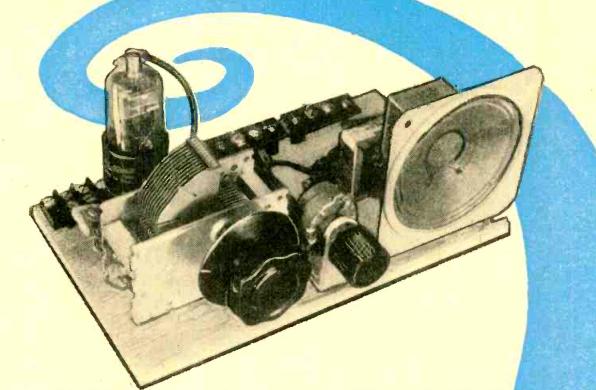
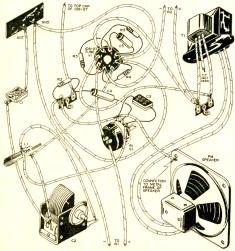
Sixty years ago, the British magazine Pracitcal Wireless, August 1955, carried the plans for this “sensitive two-valver” receiver suitable for local broadcast reception. It featured a regenerative detector and one stage of audio amplification sufficient to drive a speaker. It ran off the 230 volt AC mains, but employed a transformer to isolate the chassis. The article noted, however, that it could be used without the isolation transformer, but warned that if constructed without one, “the operator must stand on a dry board when touching metal parts of the live chassis.” The set was designed to be sensitive enough to be used with a short one-foot antenna. The article noted that neither of the alternatives, either “a few feet of wire hanging from the back” or a frame aerial, add to the decorative effects of a room.

EF50 tube, Wikipedia photo. https://commons.wikimedia.org/wiki/File:EF50.jpg By RJB1 (Own work) [GFDL (http://www.gnu.org/copyleft/fdl.html) or CC BY-SA 4.0-3.0-2.5-2.0-1.0 (http://creativecommons.org/licenses/by-sa/4.0-3.0-2.5-2.0-1.0)], via Wikimedia Commons

EF50 tube, Wikipedia photo. By RJB1 (Own work) [GFDL  or CC BY-SA 4.0-3.0-2.5-2.0-1.0.

The two tubes employed by the set were the EF50, which were probably available in large supply from surplus equipment. The tube, which has been called “the Tube that helped to Win the War,” was a major concern during the early days of the war. It was very versatile with uses in VHF and radar equipment. And it was manufactured by Philips in Holland, which was about to be overrun by the Nazis. Just before the invasion, the British managed to import a truckload of 25,000 of the tubes, along with more of the bases. Philips hurriedly dismantled its Dutch assembly line for transport to England. Members of the Philips family, along with members of the Government, escaped the day before Rotterdam was flattened aboard a British destroyer. They carried with them a wooden box containing the diamond dies that were required to make the tungsten wires inside the tubes.

Click Here For Today’s Ripley’s Believe It Or Not Cartoon


1940 Piano Salesmanship

1940Piano

In the late 1920’s and early 1930’s, the conventional wisdom was that radio would kill consumer demand for the piano. But starting in 1933, sales of the instruments began a steady climb, and reached an all-time high in 1940. In the first half of that year, over 100,000 pianos were sold. This time, the pundits gave the credit to radio, by stimulating music appreciation.

But one key factor in the piano boom was undoubtedly old-fashioned salesmanship. And this photo from Life Magazine, August 12, 1940, shows a good salesman in action. Radio brought music appreciation to the farm, and the Jenkins Music Company of Kansas City, Mo., decided to take advantage of the situation. The company had branches in Missouri, Kansas, Arkansas, Oklahoma, and Texas, and decided to cater to rural customers. About twice a week, the company would load up a truck with several pianos and a salesman and start cruising rural areas. It would find a likely farmhouse, and invite the farmer’s daughter out to the truck to see the pianos.

Here, we see sixteen-year-old Ann Williams in the truck. She already knows how to play the instrument a bit, so the salesman just stands back and lets the piano sell itself. The salesman then asks for permission to move the piano into the house “to see how it looks.” In the salesman’s experience, once the piano is moved into the parlour, it’s rarely taken out.

Ann goes out to the field and asks, “Daddy, can we buy a piano?” The salesman reassures him that he just wants to leave it there for a while, with no obligation.

Shortly thereafter, the $255 piano is in the house, and the mother has signed the contract and made the down payment.

Click Here For Today’s Ripley’s Believe It Or Not Cartoon


August 1940 Atlantic Hurricane

Savannah, Georgia, in the wake of the hurricane. AP photo, Milwaukee Journal, August 12, 1940.

Seventy-five years ago today, the South Atlantic coast of the U.S. was struck by what was described as the worst hurricane in several years. The storm probably formed in Cape Verde, and was first witnessed on August 5 between St. Martin and St. Thomas. It brought squalls of wind and rain to San Juan, Puerto Rico, before strengthening and turning northward. It then began moving westward toward the mouth of the Savannah River near Beaufort, South Carolina, which experienced hurricane-force winds on the 11th.

The hurricane warnings first went up in Charleston on early Sunday morning, August 11. The Charleston Amateur Radio Club was mobilized under the leadership of its president E. Linwood Sykes, W4AFQ. Critically, the group was lacking any emergency powered equipment, and a decision was made to move to a location where power was available. Member James Gantt, W4DFC, was an employee of South Georgia Power Company, and he secured a location adjoining a steam plant and made arrangements to run a temporary power line.

The hams carried equipment through two blocks of waist-deep water to the location and set up the equipment and antennas. Unfortunately, because of 75 MPH winds, the utility was unable to run the temporary power line. Fortunately, a nearby building with a substation had power available, and the equipment was moved again through water being blown from the river in sheets.

By 4:20 PM, the 40-meter station was on the air, and the operators attempted to make a scheduled contact with Savannah. However, power was already out in Savannah. Contact was made with U.S. Navy station NAO, and after shifting to 80 meters, traffic was flowing by Sunday afternoon.

A 160 meter ‘phone station owned by Dr. T.W. Zeigler, W4PG/W4CUS was also put into service. The first messages transmitted on 160 meters requested three line crews for the power company.

Since local telephone service was out of order, messages were initially relayed by wading through the tidewater to cars parked two blocks away. Messages were then taken to their destination. Later, Alexander McGaillard, W4GOQ and W4PG/W4CUS rigged up a low-power battery transmitter for the police department’s 1.7 MHz station, WCPD, and the police station was used to relay traffic between the city and the hams back at the power plant. Over 500 messages were handled, including Red Cross, press, power and telephone company, and personal messages.

Unfortunately, the South Carolina Governor Burnet R. Maybank erroneously stated in a radio broadcast that “unfounded lies” were being transmitted by amateur radio. However, the report in question had not been transmitted by amateur radio. Instead, it had been transmitted by a local broadcast station from its mobile unit on a frequency of 1670 kHz.

References

Click Here For Today’s Ripley’s Believe It Or Not Cartoon


Ham Bands in 1940

1940HamBands

This chart from 75 years ago, taken from the 1940 edition of the Radio Handbook, shows the bands available to U.S. hams in the days right before the war.  The bands are recognizable, and 80 and 40 have the same band edges they do today.  160 meters had just undergone a shift.  It is shown on the chart as covering 1715-2000 kHz, but the note at the bottom reveals that the band was expanded slightly to cover 1750-2050 kHz.

20 meters was slightly wider than it is today, extending up to 14.4 MHz, but 15 meters wasn’t assigned to amateurs until after the war.  Ten meters was slightly larger than today, extending up to 30 MHz.  As a compensation for losing the top 300 kHz after the war, hams were given the 11 meter band for about a decade until it was assigned to the CB service.

In the VHF spectrum, hams were assigned 56-60 MHz (5 meters), 112-116 MHz (2 – 1/2 meters), 224-230 MHz (1 – 1/4 meters), and 400-401 MHz (3/4 meters). The highest class of license (Class A) carried ‘phone privileges on 80 and 20 meters. All classes of license could use ‘phone on 160 and 10, while 40 meters was reserved for CW exclusively. Unlike today, the restrictions for lower classes of license related to mode only, and not to frequency. Class B and C licensees were allowed to operate on the 80 and 20 meter ‘phone bands, but they were limited to CW operation on those segments.

The bands above 30 MHz were open to all modes for all. FM was limited to frequencies above 58.5 MHz.

Interestingly, below 30 MHz, facsimile operation was permitted only on 160 meters, but was permitted by lower classes of license in the CW portion of the band.

The chart showed the harmonic relationships between the bands, and even noted the corresponding fundamental frequencies for particular band segments of the higher bands.

Click Here For Today’s Ripley’s Believe It Or Not Cartoon


Ronald “Dutch” Reagan, WHO Radio, 1934

1934ReaganIn 1932, Ronald “Dutch” Reagan walked into WOC Radio in Davenport, Iowa, looking for a job as a sports announcer. He was given an audition at the conclusion of which he was told, “you get five dollars and bus fare to Iowa City. You’re doing the Iowa-Minnesota game.” (Minnesota won 21-6.)

WOC was co-channel with WHO in Des Moines, and the two stations were under the same ownership. When attempts at synchronous broadcasting proved unfruitful, WHO’s power was increased to 50,000 watts and operations took place from Des Moines. Reagan was transferred there in 1933, and worked for the station until 1937, eventually becoming sports director.

Here, Reagan’s photo and brief biography are as they appeared in the April 1934 issue of Radio Stars magazine.

References


Learn How to Type Without a Typewriter!

TypewriterSimulator

If you wanted to learn how to type 75 years ago, the mere fact that you didn’t own a typewriter was no obstacle. For a mere two dollars, you could get yourself a Tuch-Rite, shown here. The Tuch-Rite was advertised in many publications, and the ad shown here appeared in Short Wave and Television magazine, August 1940.

The Tuch-Rite consisted of a cardboard typewriter keyboard, with cutouts for each letter.  Underneath each cutout was a sliding plastic piece.  The patented Tuch-Rite came with an eight-page book that promised to let you master the typewriter in no time.

The Tuch-Rite apparently held on for quite some time.  This typewriter blog shows a nicely preserved specimen from 1957.  In the 1950’s, the Tuch-Rite apparently came with a phonograph record with which the whole family could learn how to type, as a smiling mother and children are shown on the cover mastering the art of typing.

That site also includes a scan of the booklet, which comes with a stern warning not to move too quickly to a real typewriter:  “Do not attempt to practice on a typewriter until you have mastered the TUCH-RITE lesson completely.  Remember that TUCH-RITE is your learning instrument; the typewriter is your writing instrument.”

And sure enough, the Tuch-Rite is patented, as US Patent 2141747, which lists the inventor as Philip S. Gross.

I doubt if there’s much of a market for the Tuch-Rite these days, since almost everyone has a box full of old keyboards in their garage.   But cardboard technology did not end with the Tuch-Rite.  In a future post, we’ll take a look at the CARDIAC cardboard computer.

Click Here For Today’s Ripley’s Believe It Or Not Cartoon


1975 Electronic Scoreboard Project

1975Scoreboard


When I show vintage electronics projects on this site, it’s usually just for the nostalgia value, since the modern replacement is usually much better and much cheaper than recreating the old version. Today’s project, however, turns out to be an exception. It’s such a niche product that there’s really not much available off the shelf. Forty years ago this month, August 1975, Popular Electronics carried the plans for this electronic scoreboard-timer for use in athletic events. The display could be toggled between showing the score or showing the time, and the clock could count either up or down. There was provision for adding a horn to sound when the clock got to zero.

The display board shown here measured 48 by 14 inches, and would be easily visible in a large gymnasium. But the entire device, including the display, was homemade, and it could easily be adapted to a larger size.

Interior detail of the display.

Interior detail of the display.

The individual digits each contained seven 7.5 watt christmas tree bulbs, along with two extra bulbs to serve as the colon when the time was being displayed. Each segment was turned off and on by a relay, making the basic design adaptable to an even larger scoreboard.

The guts of the unit consisted of 24 integrated circuits, most 74xx series TTL. The unit included a power supply (which used the AC power at timer for the clock) for the TTL voltages, and the lamps in the display unit ran directly off 120 volts.


The article billed the parts as costing about $100. Most of the parts (or modern equivalents) should be readily available from suppliers such as Jameco Electronics, probably for less money.  While the price of a complete comparable scoreboard is probably lower today than it was forty years ago, a comparable one such as the one shown here is still considerably more expensive than the component parts for making one yourself.


Click Here For Today’s Ripley’s Believe It Or Not Cartoon