Category Archives: Radio history

1935 Two-Tube Shortwave Portable

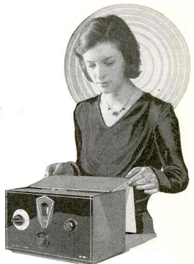
1935AugPSSW1This little two-tube portable receiver appeared in Popular Science
80 years ago this month, August 1935. It featured two type 30 triodes, one serving as the regenerative detector, with the other one providing one stage of audio amplification. With four plug-in coils, the set would tune 17 to 270 meters.

One novel feature was the inclusion of the antenna trimmer condenser inside the plug-in coil. This would allow the antenna to be separately tuned to each band, without having to fiddle with that adjustment when plugging in a different coil. The coils were changed through an opening in the top of the cabinet, with a removable cover to keep dust out.

1935AugPSSW2

Click Here For Today’s Ripley’s Believe It Or Not Cartoon


1925 Four Tube Loudspeaker Set

1925AugPM

Ninety years ago this month, Popular Mechanics, August 1925, carried the plans for this four-tube receiver. The set contained four type 201 tubes, and featured a tapped loop antenna. The set had very good selectivity by virtue of having the tapped loop. By changing the taps, the set tuned different portions of the broadcast band. On one tap, it tuned 370-550 meters (545 through 810 kHz). On another tap, it tuned
224-400 meters (750 through 1340 kHz). By breaking up the tuning in this fashion, a smaller range of frequencies was tuned by the single tuning condenser, resulting in greater separation between the stations.

The article noted that during testing in Chicago, even with the Chicago stations transmitting full blast, it was possible to receive more distant stations with the speaker.

Click Here For Today’s Ripley’s Believe It Or Not Cartoon



K2BSA in 1975

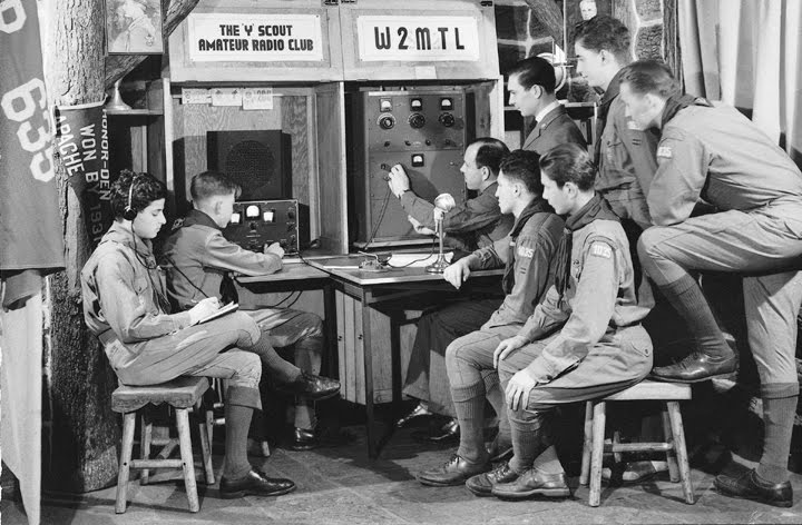
K2BSA1975Shown here is the flagship Amateur Radio station of the Boy Scouts of America, K2BSA, as it appeared 40 years ago this month, in the August 1975 issue of Boys’ Life.

As reported in the magazine, the station was then located at the Johnston Historical Museum, on the grounds of the BSA’s then national headquarters in North Brunswick, New Jersey. K2BSA is still active, although it no longer has a fixed location from which it operates. It is on the air on multiple bands and modes at BSA Jamborees. At the most recent one in 2013, I was on staff, and thousands of contacts were made around the world. In addition, the station call sign and even portable equipment are available for loan by licensed hams who are scouts and scouters for use at scouting events. In this way, the call sign is frequently heard during Camporees and other events at which scouts get a chance to experience amateur radio.

The article notes that in 1975, the station was put on the air on weekends on a monthly basis to allow visitors to speak to other Scouts around the country.

A larger reincarnation of the museum is open to the public at the National Scouting Museum near the organization’s present headquarters in Irving, Texas.

(Scouts who are working on the Scouting Heritage or Radio merit badges will find helpful information for both at my website.)

Click Here For Today’s Ripley’s Believe It Or Not Cartoon


1940 Boy Scout’s Radio

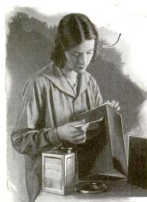
1940AugBLSeventy-five years ago, this unnamed California Boy Scout decided to bring his radio to camp. The set was one he built himself in a cigar box. The caption in this picture from the August 1940 issue of Boys’ Life reveals that the picture was taken at the Camporee of the BSA’s Oakland Area Council.

Click Here For Today’s Ripley’s Believe It Or Not Cartoon


1915 Galveston Hurricane

Flooding in Galveston after 1915 hurricane.  Wikipedia photo.

Flooding in Galveston after 1915 hurricane. Wikipedia photo.

A hundred years ago, a major hurricane hit the United States, leaving between 275-400 dead and $50 million in property damage. Adjusted for inflation, this made the storm the fourth costliest in U.S. history. The storm brought winds and heavy rains to the Leeward Islands, Puerto Rico, Hispaniola, and Cuba. Like the deadly hurricane of 1900, it made landfall in Galveston, Texas. The 1900 hurricane had caused thousands of deaths, and some lessons had been learned. In particular, in the wake of the 1900 hurricane, Galveston saw construction of a seawall. The structure was only partially effective in 1915, but still limited the destruction and saved many lives. It did cause flooding, and the beach was eroded to the point where it became an offshore sandbar.

This was one of the first natural disasters in which radio played a role in relief efforts, as reported in the September 1915 issue of Wireless Age.  The magazine, published by the Marconi Company, reports that “in a tornado [sic] which blew continuously for eighteen hours in southeastern Texas, leaving death and destruction in its path, Marconi wireless telegraphy and Marconi men showed their worth by keeping the residents of Galveston in touch with the rest of the world when all other means of communication had failed.”

Port Arthur Marconi station, 1915.

Port Arthur Marconi station, 1915.

The aerial mast of the Galveston Marconi station was destroyed, and some of the ground plates and mast anchors were swept away. But even though flood waters reached the station house, the equipment was undamaged. A Marconi superintendant in New Orleans came to Galveston to investigate, and arrived on August 19, three days after the winds had started their fury. By that time, an army transport had already established radio contact with Forst Sam Houston, 250 miles away, but with only limited success. A Marconi-equipped steamship, the Concho, was in port, and the Galveston Marconi operators reported for duty aboard that ship. On August 20, they established contact with the Marconi station at Port Arthur, Texas. This was the only reliable communications link between Galveston and the outside world, and many messages were handled for the steamship companies, the military, and the general public.

At some point, the mast at the Port Arthur station gave way, at which time messages were sent and received from another Marconi-equipped steamer, the Wild Duck.

After unleashing its fury on Texas, the storm turned toward the Ohio Valley, finally fading out on August 23.


Click Here For Today’s Ripley’s Believe It Or Not Cartoon


Philco Model 41-841

20150814_102532

Many Point Scout Camp is owned and operated by the Northern Star Council of the Boy Scouts of America, and has been in operation since 1947. Local scouts and scouters don’t always realize what a gem it is, and those in other parts of the country are often unable to comprehend its sheer size. It covers 2400 acres and nine miles of shoreline on two lakes, Many Point and Round Lake. At 15 miles per hour, it’s about a 30 minute drive from one end of the camp to the other, and it’s another 30 minute drive to the nearest full-service gas station or supermarket. Therefore, it provides a real wilderness experience to thousands of scouts.

Because of its size, it lies on land that has seen its share of history, and since 1996, it has included a very nice History Center to showcase some of that history. In addition to the scouting that’s taken place there since 1947, the museum contains displays regarding the earlier users of the land. Therefore, it has displays about the Native Americans, the fur traders, the loggers, and the sportsmen. In the first half of the 20th century, several resorts were located on the land where Many Point is now located, and one of these is recreated in the museum.   (A complete guide to the History Center is available online.)

20150814_102540What caught my eye, of course, was the Philco portable radio shown here. The set, it turns out, is a Philco model 41-841, which would have been manufactured shortly before the War in 1941. So as far as the age of the set, it’s consistent with the display.

It is a battery-operated portable, which ran off a 3 volt A battery for the filaments, and a 90 volt B battery. It was also capable of running off household current, using a 117Z6G rectifier for the B+. When run on household current, the filament voltage was provided by simply dropping the rectified power supply through two resistors. The set’s schematic can be found at this link, and you can read more discussion at this link and this link.

In addition to the rectifier, the set has four tubes, a 1A7G, 1N5G, 1H5G or 1LD5, and 3Q5G. It’s a fairly typical superheterodyne, and has provisions for external antenna and ground. At night, the fishermen sitting around the table would be able to hear scores of stations from the Twin Cities, Chicago, and around the country. One of the strongest stations at night probably would have been WDGY, whose nine-tower array cast a formidable signal to the north.

During the daylight hours, the set would probably get a fairly good signal from WDAY in Fargo, North Dakota.  In addition, it might possibly have pulled in 50,000 watt WCCO or then 25,000 watt KSTP in the Twin Cities during the daylight hours.


Amateur Station 2GT, 1915

2GT1915

A hundred years ago, this state-of-the-art amateur station, 2GT, was pictured in the August 1915 issue of The Wireless Age.

The owner of the station is not identified, but the accompanying article notes that all of the apparatus was built and designed by three young men. The lower panel is the receiver, and the article describes the coils and variable condensers used. It notes that three detectors are available: “silicon, antimony, and valve,” all switchable from the front panel. The antenna was a 250-foot three-wire inverted “L”. The transmitter was a rotary gap, with a transformer capable of supplying 13,000 volts.

In the 1914 call book, the station is listed as being licensed to one John W. Vegessy, 435 E. 6th Street, New York.


1950 Marine Receiver

1950RDFThe mariner shown here is demonstrating the Lear Model P10A “Learavian” portable receiver designed for marine and aviation applications. The six-tube set could operate form 115 volts AC or DC, or from the enclosed rechargable battery, with a charging time of only 30 minutes. In addition to the standard broadcast band, the set also tuned the 195-415 kHz longwave band and the 1960-5750 kHz shortwave bands for reception of all aviation and marine broadcasts and navigational aids. With an external directional antenna, the set was suitable for radio direction finding.

The accompanying article noted that service technicians operating near yacht basins or airports could investigate the possibility of capturing the installation and repair business represented by the set.

The photo appeared on the cover of Radio News 65 years ago this month, August 1950.

Click Here For Today’s Ripley’s Believe It Or Not Cartoon


Sayville Radio Tower, 1915

SayvilleTower1915

A hundred years ago this month, the August 1915 issue of Electrical Experimenter magazine
shows the giant radio tower at Sayville, Long Island, superimposed over a scene of the war raging in Europe. As discussed in earlier posts, the station was owned by Germany’s Telefunken System, which had been placed under German government control, and communicated with the counterpart station in Nauen, Germany. In August 1914, none other than Hiram Percy Maxim advised the U.S. Government that the station had been transmitting coded messages in violation of U.S. neutrality. The German-controlled stations in the U.S. had been subsequently placed under the watchful eye of the U.S. Government.

The accompanying editorial by Hugo Gernsback notes the ease with which the Germans could use the station to send coded messages to ships and U-boats at sea, under the guise of innocuous business correspondence.

Click Here For Today’s Ripley’s Believe It Or Not Cartoon


1955 British Two-Valve Receiver

1955AugustPracticalWireless

Sixty years ago, the British magazine Pracitcal Wireless, August 1955, carried the plans for this “sensitive two-valver” receiver suitable for local broadcast reception. It featured a regenerative detector and one stage of audio amplification sufficient to drive a speaker. It ran off the 230 volt AC mains, but employed a transformer to isolate the chassis. The article noted, however, that it could be used without the isolation transformer, but warned that if constructed without one, “the operator must stand on a dry board when touching metal parts of the live chassis.” The set was designed to be sensitive enough to be used with a short one-foot antenna. The article noted that neither of the alternatives, either “a few feet of wire hanging from the back” or a frame aerial, add to the decorative effects of a room.

EF50 tube, Wikipedia photo. https://commons.wikimedia.org/wiki/File:EF50.jpg By RJB1 (Own work) [GFDL (http://www.gnu.org/copyleft/fdl.html) or CC BY-SA 4.0-3.0-2.5-2.0-1.0 (http://creativecommons.org/licenses/by-sa/4.0-3.0-2.5-2.0-1.0)], via Wikimedia Commons

EF50 tube, Wikipedia photo. By RJB1 (Own work) [GFDL  or CC BY-SA 4.0-3.0-2.5-2.0-1.0.

The two tubes employed by the set were the EF50, which were probably available in large supply from surplus equipment. The tube, which has been called “the Tube that helped to Win the War,” was a major concern during the early days of the war. It was very versatile with uses in VHF and radar equipment. And it was manufactured by Philips in Holland, which was about to be overrun by the Nazis. Just before the invasion, the British managed to import a truckload of 25,000 of the tubes, along with more of the bases. Philips hurriedly dismantled its Dutch assembly line for transport to England. Members of the Philips family, along with members of the Government, escaped the day before Rotterdam was flattened aboard a British destroyer. They carried with them a wooden box containing the diamond dies that were required to make the tungsten wires inside the tubes.

Click Here For Today’s Ripley’s Believe It Or Not Cartoon