Category Archives: Radio history

Courtney’s Radio Service, Stratford, Conn., 1943


1943SepRadioRetailingShown on the cover of Radio Retailing Today 75 years ago this month, September 1943, is Mrs. Wallace Courtney, the wife of the owner of Courtney’s Radio Service in Stratford, Conn. When a representative of the magazine entered the shop, he was greeted by Mrs. Courtney, who was busily engaged in her work of servicing radios. When the reporter asked about the set she was working on, she reported that the rectifier was intermittently glowing red hot. After some poking around, she found a high voltage lead with frayed insulation that had been shorting out against the chasis.

1943Aug30BC2Mr. Courtney was working in a war plant installing radios in airplanes, and left the shop in the able hands of his wife, who juggled the business with caring for the couple’s twelve-year-old son, who was said to be earning good marks. It was her quiet, pleasant voice that answered the phone when customers called. She wasn’t able to make service calls, but when customers brought in a set, she would get it repaired as fast as humanly possible.

According to the magazine, Mrs. Courtney was “typical of a lot of American wives and mothers, who without any fuss or furore, have stepped calmly into their men’s places for the duration in whatever capacities the jobs may call for.” She ran the shop during the day, and in the evening helped her husband work out any repair problems in whatever hours he could spare.


1968 Instant Battery

1968SepEE1Sixty years ago, the September 1968 issue of Electronics Illustrated carried a review of this interesting product, an emergency battery.

Batteries have a finite shelf life, so to extend it, this dry cell was sold dry. In its dormant state, it had a guaranteed shelf life of five years. When needed, you added the electrolyte, which could be any water-based liquid. In the test, the magazine used window washer fluid, but almost any liquid could be used, such as soda, or what the magazine euphemistically called “second hand beer.” After activation, the battery was good for 72 hours.

The battery was available for $5.95 from the Globe Battery Division of Globe-Union, Inc., Milwaukee. A matching lantern was available for $10.95.

Since modern alkaline batteries have a long shelf life, it’s probably not necessary to have this battery today. The best modern equivalent is probably the one shown here, which allows a cell phone or other USB device to be charged with four AA alkaline batteries.

Another option for emergency charging is s standard 12 volt USB charger.  Even if the car battery is unavailable, in most cases, these chargers consist of little more than a voltage regulator, so if they’re hooked to any source of more than five volts, they can be used in an emergency.  So if you desperately need to charge your phone, you can use one of these adapters, along with four flashlight batteries or a 9-volt battery, as demonstrated in this video:

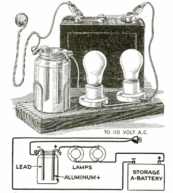
For another emergency battery that can be made using household goods, see our earlier post.


NBC Radio, Canton Island Eclipse Coverage, 1937

1938Sep5LifeThis picture appeared in an RCA advertisement in Life magazine 80 years ago today, September 5, 1938. It shows NBC engineers Marvyn Adams and W.R. Brown along with NBC announcer George Hicks broadcasting live from Canton Island (sometimes spelled Kanton) in the South Pacific.

1937 Eclipse from Canton Island. Wikipedia image.

They were on the island as part of a joint expedition by the U.S. Navy and the  National Geographic Society for the solar eclipse of June 8, 1937.  The NBC eclipse coverage was transmitted from this “ultra-high frequency transmitter” to the USS Avocet anchored at the island, and from there to the RCA station at Point Reyes, California, where it went by wire to the NBC Blue Network.

According to the ad, the island would possibly “play an important role in transpacific air transport service,” a prophecy which proved true, as the island served as a stop for PanAm’s Pacific Clipper service to New Zealand, which ran from 1940 until the war, and then again from 1946.

The Navy-National Geographic expedition, in addition to observing the eclipse, placed a monument on the island to bolster the U.S. claim to sovereignty over the island. This was disputed by the British, who also had a ship anchored for the eclipse. Reportedly, the British ship, the HMS Wellington, fired a shot across the bow of the USS Avocet, which reciprocated. The two commanders called a truce pending further instructions from their command, and the two parties observed the eclipse together.

During the war, the U.S. Navy built a 6230 foot airstrip on the island, which was defended by as many as 1200 combat forces, but was never attacked by Japan.  The island now forms part of the Republic of Kiribati.  As of 2010, it had a population of 24.

The island was most recently in the news that year after a yacht stopped en route from Honolulu to Fiji and discovered that the islanders were desperately short of food, an expected supply ship never having arrived.  The islanders had been living on fish and coconuts for several months, and the yacht owner used his satellite phone to contact the U.K. Coast Guard, which contacted the U.S. Coast Guard to arrange relief supplies.


Transatlantic TV DX: 1958

1958SepRadioElecYesterday, we showed a regenerative preamplifier from 1968, designed by Hartland B. Smith, W8VVD, currently licensed as W8QX.  We promised that we would bring you another article by this prolific writer which appeared ten years earlier, in the September 1958 issue of Radio Electronics.

Smith begins the 1958 article by pointing out that he had been a licensed ham for 18 years and had his share of exciting DX contacts, but that he could “honestly say that none of these gave me quite as much a thrill as when I first saw an indentifiable transmission directly from London on the screen of my own TV set.”

And as shown by these pictures, that’s exactly what he did. The winter of 1957-58 was at the peak of the greatest solar maximum in recorded history, meaning that the maximum usable frequency (MUF) was frequently going above 40 MHz. This opened the possibility of pulling in Transatlantic TV signals, which is exactly what Smith set out to do.

Receiving the audio of British and French television signals was a relatively simple matter. The London and Belfast stations were on 41.50 MHz, and Caen, France, was on 41.25 MHz. Armed with nothing more than a prewar FM receiver, he was easily able to hear the audio. (Indeed, it wasn’t uncommon for American hams to listen to British TV audio on their six meter receivers.)

But being able to watch the video posed a much greater challenge. European TV used both different frequencies and different standards from American TV, so an American TV could not be used without some modification. So Smith set out to make the modifications. He focused on trying to pull in the powerful London station, which transmitted on 45 MHz with 200 kilowatts. The French station’s video was on 52.4 MHz, which was likely to be above the MUF even if the audio were booming in.

The first relatively modest challenge was the frequency, which was lower than that tuned by American sets. This was accomplished with a simple converter consisting of a single 12AT7 tube. With an oscillator frequency of either 33 or 123 MHz, this would bring the British signal to American channel 5, which was unused in his area. The antenna consisted of a two-element beam in the attic for video, with a folded dipole for the audio receiver.

Lisajous pattern on scope showing equal frequencies. Wikipedia image.

Tuning in the signal was one thing, but getting a visible picture required that the set be modified internally. The first issue was the horizontal sweep frequency, which was 15,750 Hz in the American set, but 10,125 Hz on the British signal. He did this by using an audio oscillator to produce the required 10,125 Hz signal, and feeding this and the horizontal oscillator into a scope. He then adjusted the horizontal and added components until the frequencies matched, as shown by a circular lisajous pattern on the scope.

The British vertical frequency of 50 Hz was deemed close enough to the American 60 Hz to not require any modification.

The final problem was that the video carrier in Britain was opposite of that used in the U.S. To correct this, he modified the video detector by reversing the cathode and plate.

With the modifications made, it was just a matter of listening on 41 MHz and waiting for the audio of the European signals to appear. This meant that the band was open, and it was time to turn on the video receiver.

This was a fairly elaborate process. The first step was to turn on the converter, and adjust the converter frequency until the “familiar out-of-sync zig-zag lines denoting a video carrier” appeared on the screen. (Anyone who watched TV in the 1970’s or earlier knows exactly what he means. If you’re too young to remember, click here for an example.)  At that point, the vertical hold would stop the picture from moving vertically, and then the horizontal hold control was adjusted (which might require some internal adjustment to make sure the control was in range). As he put it, “TV dx tuning is an art that is a little hard to describe on paper. It is best learned by experiment.”

He pointed out that picture quality would never be perfect. For one thing, there would almost always be multipath interference, since signals through the ionosphere might travel numerous paths. He noted that the ghosting problem might sometimes be acute. During one televised tennis match, he reported seeing at least 30 players batting 15 balls back and forth. But occasionally, the ionosphere would settle down momentarily, resulting in the identifiable images shown here.


1968 “DX Devil”

1968SepEEThe young man shown on the cover of the September-October 1968 issue of Elementary Electronics, along with his loyal beagle, are taking a break from baseball to pull in some DX on their Heathkit GR-43 portable shortwave receiver.

But the portable was pulling in DX from all corners of the world, since it had been effectively souped up, thanks to the “DX Devil” described in the magazine.

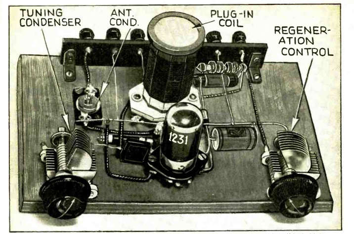
The DX Devil was a one-transistor (MPF-107 FET) regenerative preamplifier, which gave 40 dB gain from 3-30 MHz.  In addition, it eliminated images, since the tuning was sharp enough to eliminate the offending signal 910 kHz away.  And since it was regenerative, it also served as a Q-multiplier to vastly increase the set’s selectivity.  The author noted that most shortwave sets selling for less than $75 lacked a tuned RF stage, and that the addition of the DX Devil would vastly increase both sensitivity and selectivity.

Three plug-in coils allowed for band selection.  The article noted that the unit’s performance would be especially noticeable on higher frequencies.  Tuning was accomplished with a vernier dial to allow amplification of a very narrow bandwidth.  In operation, the regeneration control was set to just below the point of oscillation, ensuring maximum gain.

The author noted that the performance of the DX Devil would be inversely proportional to the quality of the receiver used: “The worse your set is, the more startling will be the results.” He reported that on a pre-WW2 receiver, 28 MHz signals were lifted from inaudibility to 100% copy. But even on a modern dual-conversion superhet, he reported much more readable signals, with the S-meter jumping 20-30 dB.

Operation of the unit would require two hands.  First, you would tune the receiver to the desired frequency.  Then, you would rock the tuning control back and forth while slowly increasing the regeneration.  I imagine that it would take a bit of practice, but eventually, you would find that the signal strength had jumped considerably.

Despite being concealed in the cover photo, the DX Devil did require a direct connection between an external antenna and the antenna terminals of the receiver.  The four diodes shown in the circuit were to provide protection in case the DX Devil was used in close proximity to a transmitter, or in case of static discharges.  At the low signal levels, they would have little effect on the circuit, but when presented with a stronger signal, they would provide a low-impedance path to ground.

1968SepEEschematic

The designer of this circuit is a familiar name to readers. The circuit was designed by the author of the article, Hartland B. Smith, W8VVD, currently licensed as W8QX.  He was first licensed in 1941, and was the author of many construction articles, such as one for a steam-powered transmitter previously featured here.  He was also the creator of the HART-65 transmitter.  A link to some of his websites can be found at the steam-powered transmitter post.  Tomorrow, we’ll bring you an even more interesting article by the same author from 1958.

Most times when I post an illustration such as this of a completed project in use, I need to take a certain amount of poetic license to name the characters.  So ordinarily, I would probably assign the name “Junior” to the young SWL, and “Fido” to his canine companion.  But in this case, such artistic license is not necessary, since the magazine gives the full name of the SWL, namely, one Gary Bulger.  And the dog’s name is Gladys.

I wasn’t able to track down Mr. Bulger, who I’m guessing lived in the New York area in 1968, since that’s where the magazine was based.  But people Google their names from time to time, and if you are the young Mr. Bulger shown in the photo, we would love to follow up with your recollections of this photo.  Please comment below or e-mail me at clem.law@usa.net.


Copper Coil Winding Hint

1938SepSWcraftThe September 1938 issue of Short Wave & Television shared this hint for winding transmitter inductors from copper tubing, without kinking the copper. Before winding, place a cork in one end and fill the tube with sand. Then, plug the other end. The sand exerts an internal pressure which keeps the tubing from collapsing.

The idea had been sent in to the magazine by one Donald E.A. Rose.


Lew Brock, WCCO 1943

1943Aug30BCThis ad for WCCO Minneapolis appeared in Broadcasting magazine 75 years ago today, August 30, 1943.  It reminded advertisers that the station’s 6-7 AM program, time on which could be booked at the early morning rate, was hosted by Lew Brock, who had a loyal following with the station’s loyal listeners.

According to the ad, former vaudeville star Brock emceed the “Sunrisers” program, which included an orchestra and other musical regulars.


1948 One Tube Reflex Reciver

1948AugRadioScienceSeventy years ago this month, the August 1948 issue of the Australian magazine Radio Science carried this circuit for a one-tube reflex receiver capable of driving a speaker.  The circuit called for a 1C3GT tube, but noted that any one-volt tube could be used with an adjustment of the bias voltage.


1958 Popular Electronics Two-Transistor Transmitter

1958AugPESixty years ago this month, before QRP was cool, the August 1958 issue of Popular Electronics carried the plans for this QRP transmitter for 15, 11, and 10 meters.  The set was dubbed the Semiconductor Space Spanner. The two-transistor transmitter had an input power of 96 milliwatts. The author, Don Stoner, W6TNS reported contacts all over the continent and as far away as Hawaii. While some of those contacts were pre-arranged, many were the result of a normal CQ.

The cost of the parts was said to be $19, less crystal. A 40 meter crystal was used on 15 meters, although the circuit pulled the signal somewhat below the exact third harmonic.

The circuit used a 2N371 transistor as oscillator, feeding the 2N370 final amplifier.

If the author’s name looks familiar, readers will recall that he was the designer of an early CB rig which served as the prototype of the Heathkit CB-1 and “Benton Harbor Lunchbox” transceivers for 2, 6, and 10 meters.

1958AugPE2