 Readers of this blog might remember the name Hartland Smith, W8VVD, currently licensed as W8QX. We previously featured his steam powered transmitter, which appeared in Popular Electronics in 1965. A number of his projects appeared in PE and other magazines, and the one showed here appeared in Popular Electronics 50 years ago this month, October 1967.
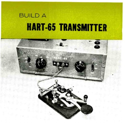
It was a transmitter for the novice which put out a very respectable 65 watts on 80 and 40 meters. It was an updated version of the author’s “Hart 25” transmitter which appeared in the magazine in 1955. Despite the increased power, the new version boasted the same price of about $20 for all of the parts. The 1955 version had used a 6W6 tube to put out about 25 watts, along with a 5Y3 rectifier in the power supply.
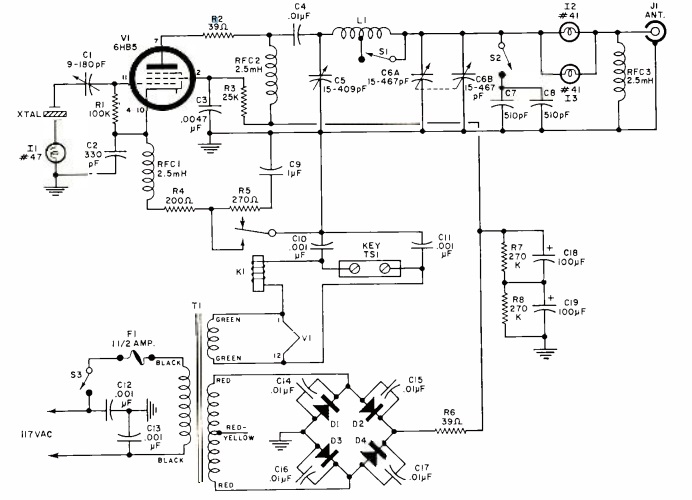
The 1967 version employed a 6HB5 TV horizontal amplifier, which was said to be highly efficient at cranking out RF. Tuning was accomplished by the simple expedient of tuning the pi network for maximum brightness of the pilot lamp. Another pilot lamp was provided for monitoring the current to the crystal, since too much current could fracture it. The article noted that smaller HC6/U crystals (and almost any modern crystal designed for solid-state circuits) should not be used because they would overheat, drift, and possibly shatter.
Cathode keying was used, but since the would mean as much as 700 volts across the key, a 6 volt relay was used for safety. The built-in power supply used a semiconductor bridge rectifier.
Smith recommended a full-size dipole antenna for the transmitter, rather than trying to use it with a random wire or multi-band antenna. He did have one insight that I independently discovered years later: “If an 80-meter dipole is too long for your piece of real estate, don’t hesitate to bend it around corners, or even droop the ends. Whatever the final arrangement, make certain that you have a total of 125′ of wire in the air.” As you can see from my fan dipole from the June 2010 issue of QST, I’m not adverse to introducing a few zig-zags into an 80 meter dipole in order to squeeze it only a city lot.
He notes that the pi network should be adequate for keeping harmonics to a minimum. However, he also advises that if TVI is a problem, a low-pass filter in line with the antenna is in order. With today’s more stringent requirements for spectral purity, it would probably be a good idea to add the extra filtering even in the absence of TVI reports.
He reported that on the air, he worked numerous stations throughout the U.S. and Canada on both 80 and 40 meters. The rig had a “click-free pure d.c. note that was a joy to copy.” It was reported to be “rock-steady” on 80 meters, and “its 40-meter stability compares favorably with that of many low-cost VFO transmitters presently on the market.”

Hart-75 Transmitter. QST photo.
In addition to writing articles, Hartland Smith was the proprietor of Hart Industries, which produced a number of kits (and a few wired sets), including the Hart 25. The 1955 Popular Electronics article included the address for Hart Industries for the kit, which included the pre-punched chassis. Another Hart Industries kit was the similarly named Hart-75 from 1956. That transmitter was reviewed by Lew McCoy, W1ICP, in the February 1956 issue of QST. Even though the basic circuit was quite different from the PE transmitter (it used a 6AG7 oscillator and 807 final), it did have one common design feature, namely, the use of the relay for keying.
The 1956 model had an interesting twist, in that a DPST relay was used, keying the oscillator and amplifier almost simultaneously. But the circuit used something called “differential keying.” The contacts of the relay were set so that the oscillator came on slightly before the amplifier, and stayed on longer. The result was that chirp was greatly reduced.
The Hart-65 does not use cathode keying. It uses _B-minus_ keying, which is why the “cathode” connection keyed by the relay sits at 700 V — the power supply’s no-load voltage. — at key up. What causes this is keying the ground lead of the tube’s 100 k grid resistor along with the cathode. To change the circuit to use cathode keying, connect the cathode end of the grid resistor to common. Key-up voltage will then be the tube’s cutoff voltage — probably 50 to 80 V, depending — and not the full output voltage of the power supply.