Here’s what was on the radio 75 years ago today. These listings appeared in the Milwaukee Journal, April 10, 1944 and show programs for April 10 and 11. (You can click twice on the image above for a larger version.)
Here’s what was on the radio 75 years ago today. These listings appeared in the Milwaukee Journal, April 10, 1944 and show programs for April 10 and 11. (You can click twice on the image above for a larger version.)
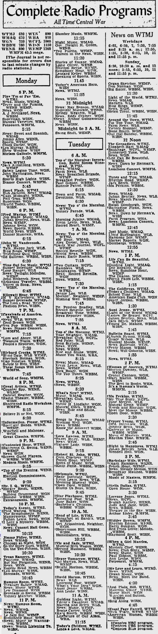
 During World War II, many radio tubes were unavailable, and the magazines were full of ideas on how to cope. The April 1944 issue of Popular Mechanics showed how to make adapters to use similar tubes that might be available, but used different base types.
In particular, the magazine pointed out that loctal tubes were often available. Therefore, the adapter shown here allows a loctal tube to be plugged into a standard octal socket. The bottom half of the adapter was a defunct tube (probably the one being replaced), and the top half was a socket to match the new tube.
 Eighty years ago this month, spring had sprung, and the cover of the April 1939 issue of Radio Retailing offered the reminder that a sure sign of spring was broken antennas. It was time to get out and fix them, and hopefully put a few dollars in the dealer’s pocket.
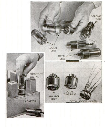
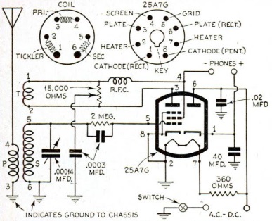
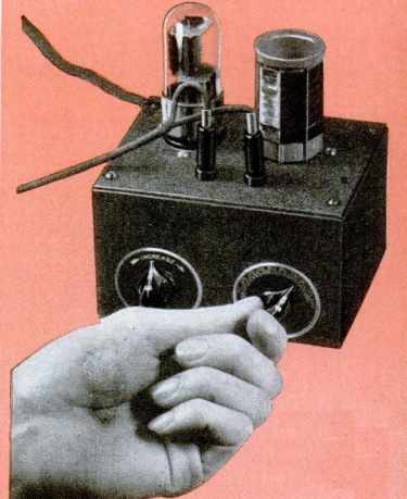 Eighty years ago this month, the April 1939 issue of Popular Science showed how to put together this simple one-tube regenerative receiver.
The set employed a 25A7GT tube, which combined rectifier and pentode. The article noted that the set had a range of about a thousand miles on the broadcast band, but the parts list called for “a set” of plug-in coils. So there’s no reason why the set, with appropriate coils, couldn’t pull in shortwave signals.
The set uses the familiar “curtain burner” line cord to step down the filament voltage. Also, if you’re considering building such a set, there is an important safety reminder. Depending on which direction the line cord is plugged in, there’s a possibility that the chassis is hot. Even if you use a polarized cord to make sure the chassis is neutral, then the rectified line voltage is hooked directly to the headphones. So if you plan to recreate this particular set, please use extreme caution.
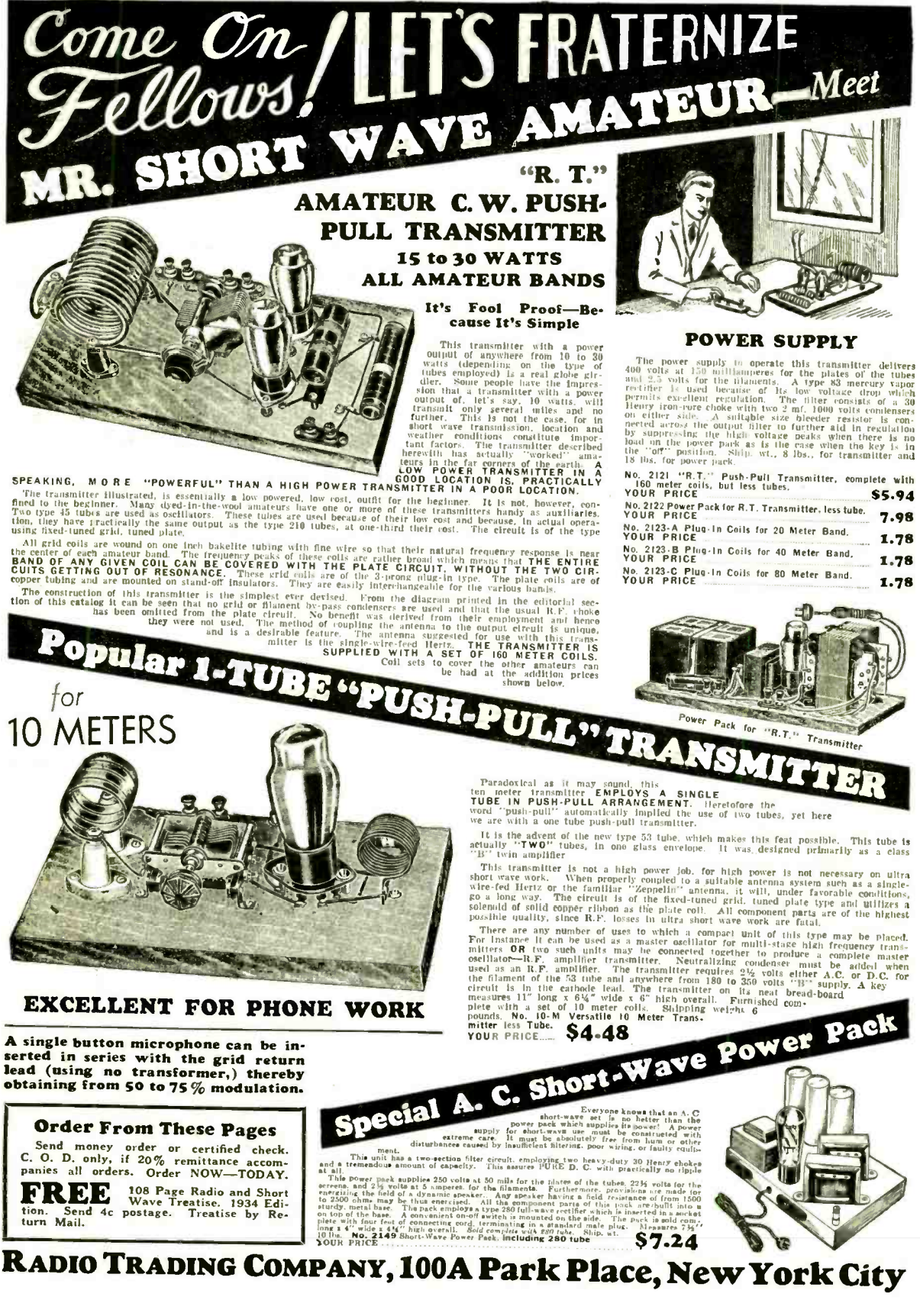 This ad for the Radio Trading Company, 100A Park Place, New York, appeared 85 years ago this month in the April 1934 issue of Short Wave Craft. The top transmitter put out 15-30 watts, depending on tubes used, and retailed for $5.94. This price included a set of coils for 160 meters, but did not include tubes. Coils for other bands were also available. The accompanying power supply sold for $7.98, but did not include the rectifier tube.
The transmitter at the bottom was for ten meters, and ran a dual triode push-pull.
 Occasionally, the radio art produces a true visionary who is many years ahead of his time. For example, most amateurs are familiar with the groundbreaking work of Larsen E. Rapp, WIOU.
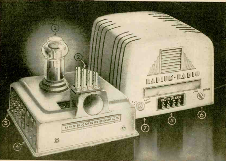
Another similar visionary appeared on the pages of Radio Craft, in the magazine’s April 1944 issue. There, Mohammed Ulysses Fips writes of the Radium Radio receiver. The set was so powerful that it required but a single tube to achieve loudspeaker volume. But the most revolutionary aspect of the set was the fact that it required no power source. Since the radium in the tube emitted radiation for thousands of years, no further power supply was necessary. And because of the power of the tube, very few other components, such as capacitors or resistors, were required. Some of Fips’ designs are shown here. As you can see, one incorporates an alarm clock feature and an ad blocker.
As might be expected, Fips proved a threat to various commercial interests, such as the Big Radio Companies, the Big Tube Companies, and the Big Battery Companies. Fips faced persecution and even kidnapping. In fact, his pet aardvark had also been kidnapped by one of the Big Radio Companies. Because of the threats, Fips decided to publish his ideas rather than attempt to personally profit from them.
For those wishing to duplicate Fips’ work, the schematic is shown below. I haven’t been able to locate the required RA-RA 4-1 tube, although like anything, I assume they show up on eBay occasionally.

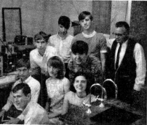
Shown here are members of the radio club of William Henry Harrison High School, Evansville, Indiana. The picture appeared in the March 1969 issue of Popular Electronics, which noted that the school claimed to have the only high-school amateur TV station. The club members built the station from modified military and commercial equipment and transmitted with 100 watts on 445 MHz from an 80 foot tower.
The magazine noted that 26 members had general class licenses.
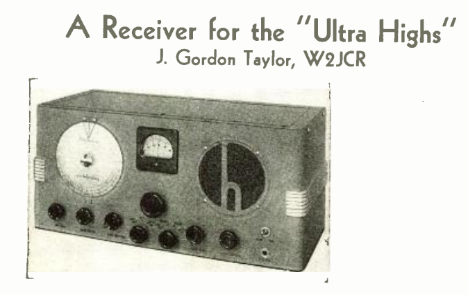 The March 1939 issue of Radio and Television magazine carried this review of the new Hallicrafters Skyrider 5-10 receiver for the “ultra highs,” which at that time meant 25-66 MHz, in two bands, 25-44 and 38-66 MHz.
This, of course, covered the prewar FM band, but the biggest market for the receiver was hams, since the set covered the 10 and 5 meter bands. The set contained nine tubes, including one RF stage and two IF stages. The IF was 1600 kHz, and the second IF tube also served as BFO.
The RF stage was a new UHF tube, the 1852. The reviewer, J. Gordon Taylor, W2JCR, noted that the new tube “really provides respectable gain.” Each stage was separately shielded. To put the new receiver through its paces, the reviewer used it at his home station and at the stations of a number of other New York hams with good 5 and 10 meter equipment. It outperformed all of the existing receivers, with one exception. That exception was the station of W2AMJ, which consisted of a Hallicrafters SX17 with a homebrew 5 meter converter. The review noted that between the receiver and converter, the W2AMJ setup had a total of 15 tubes, as compared to nine with the 5-10. The 5-10 was able to pick up all of the same stations, but the homebrew converter and receiver had greater volume.
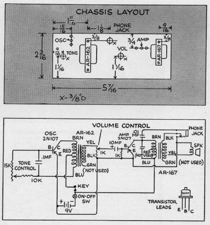
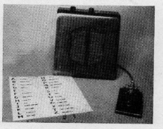 Sixty years ago this month, the March 1959 issue of Boys’ Life showed scouts how to put together this two-transistor code practice oscillator. Powered by six penlight cells, one 2N107 transistor served as oscillator, with the other as an audio amplifier. So chances are, the output was both clean and loud. The set featured both tone and volume controls, and had provision for headphones or a built-in speaker.
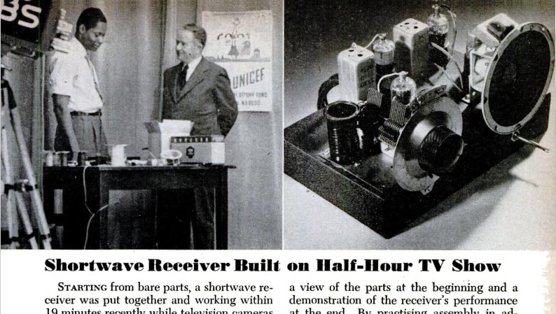 Seventy years ago was the Goolden Age of Television, as conclusively proven by this article in the March 1949 issue of Popular Science. It details a most interesting program, namely, a live play-by-play of the construction of a shortwave receiver.
Starting from scratch, sound man Rudy Winston (shown at left in the photo) got the set working in 19 minutes while the live cameras of WCBS-TV looked on. The program was 30 minutes, but Winston had only 25 minutes, since the script called for a demonstration. But he was pulling in overseas stations with six minutes to spare.
The feat took place on the station’s “United Nations’ Casebook” program. The purpose was to “dramatize one of the world’s greatest needs–inexpensive, sturdy shortwave receivers.”
Today, inexpensive sturdy shortwave receivers, such as the ones shown below, are readily available. The models shown here can operate from power sources including solar or hand crank, meaning that they can bring shortwave reception to any point on earth. What we need more of are television shows demonstrating how they can be put together.
And, of course, if you get booked to go on TV to build a shortwave receiver, one of these kits will probably allow you to complete it in the course of a half-hour program: