Category Archives: Radio history

1939 Four Tube Regen

1939AprPS1The young man shown here is diligently hitting the books, but he’s also entertaining himself, thanks to the combination radio-bookends described 80 years ago this month in the April 1939 issue of Popular Science. The radio is built into one bookend, and the speaker into the other. The two ends can fold down for easy transport, as shown below.

1939AprPS2

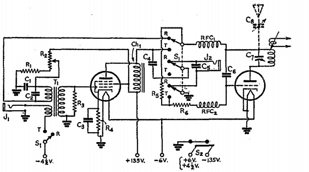
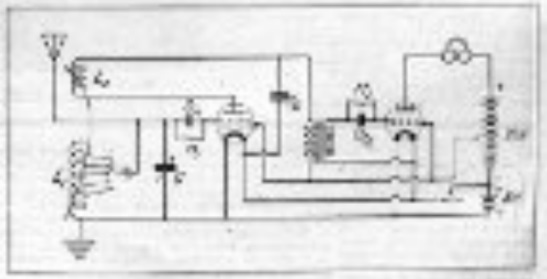
The circuit itself contains four tubes. A 6SJ7 pentode serves as regenerative detector, with a 6SF5 and 25A6 as audio amplifier. A 25Z6 full-wave rectifier rounds out the tube compliment. According to the text, the antenna is built in, although the schematic shows connections for external antenna and ground for pulling in the distant stations.

1939AprPS3


Notre Dame de Paris Sound System & Air Raid Sirens

x

NotreDamePA

Incendie Notre Dame de Paris

2019 fire.  Wikipedia photo:  LeLaisserPasserA38 [CC BY-SA 4.0], via Wikimedia Commons

Construction of the Cathedral of Notre-Dame de Paris, which is burning today, began in 1160 and was largely completed in 1260.  It was wired for sound in about 1925, as shown in the illustrations above.  At left, a microphone is visible above the pulpit.  At right, a speaker is mounted on a pillar near the chancel.  One of the cathedral’s distinctive rose windows is visible in the background.  The pictures appeared in the July 1925 issue of Radio News, which reported that the then-700-year-old cathedral had finally been modernized.  According to the magazine, the speakers were installed “so that the congregation may hear the services.”

Another picture, shown below, is also of Notre Dame, but is not immediately recognizable as such.  From the 1918 issue of Electrical Experimenter, the picture shows air raid sirens installed atop one of the towers.  For an look at a 1914 air raid on Paris, see our earlier post.

1918AugElecExp


Arnie Coro, CO2KK, 1959

1959AprPE

Castro in Washington, 1959. Wikipedia photo.

Sixty years ago today, on April 15, 1959, Cuban dictator Fidel Castro began his eleven day tour of the United States. But as you can see from the page of that month’s Popular Electronics shown above, another familiar Cuban name was making his mark in the U.S.

The article is a one-page feature on TV DX’ing, and offers little detail. The image at the top is a screen shot of WPST-TV in Miami, captured in Havana, Cuba. And the author of the article is none other than Arnaldo “Arnie” Coro, Jr., CO2KK, one of the founders of Radio Havana Cuba, and a popular host of the station’s DX program.


Sentinel Model 170-BL, 1939

1939AprRadioRetailingSentinelEighty years ago this month, the April 1939 issue of Radio Retailing carried this ad for Sentinel portable sets, featuring the country’s lowest priced battery set, the model 170-BL.  The three-tube superhet sold for $14.95, including battery, and featured a tube lineup of 1N5G, 1N5G, and 1A5G.  Filaments ran off a 1.5 volt A battery, with a 90 volt B battery.


Henry L. Carter, Jr., W8FTB

1934AprSWcraftShown here in the April 1934 issue of Short Wave Craft magazine is the well equipped station of Henry L. Carter, Jr., W8FTB, 45 Sheldon Terrace, Rochester, N.Y., at the time, the youngest licensed amateur in the United States. Carter was first licensed at the age of 10 on January 14, 1932. He got his first station set up with the assistance of his father, ex-8BOW, who had been licensed in 1923. The transmitter was a crystal controlled three tubes on 3530 and 3840 kHz. Carter reported that he could copy “20 per, and send ‘plenty fast.'”

He had worked stations throughout the U.S., Canada, and Mexico, and held an Army Amateur Radio Station appointment. He was also the youngest member of the Scout Amateur Radio Net, and as you can see from the uniform, he kept himself busy with Scout work. His troop had organized a radio club consisting of sixteen members.

According to a Sept. 27, 1939, article in the Rochester Times Union contained in this scrapbook,
Carter, then residing at 297 Plymouth Ave. S., joined the Army Signal Corps at the age of 18.

I wasn’t able to find any reference to Carter after the War.  If he had gone back to Rochester, his call would have become W2FTB, but I wasn’t able to find any reference to him holding that call.  He would be about 97 today, so if Mr. Carter or a relative is out there, we would enjoy very much hearing from you to follow up.


1949 Two Tube Broadcast Receiver

1949AprPM1Seventy years ago this month, the April 1949 issue of Popular Mechanics showed how to put together this simple two-tube broadcast set. Running off AC power, the set would drive a loudspeaker. It used many of the same parts as a one-tube set published in the January issue, allowing the radio student to upgrade the simpler set.

A 6J6 dual triode carried out the RF duties, with a 6AK6 pentode AF amplifier driving the speaker. The set employed a selenium rectifier.

One unobtainium part is the permeability tuner, similar to the one used in a 1948 Popular Science receiver.

1949AprPMschematic


Milwaukee Radio Listings, April 10, 1944

1944Apr10MilJournal

Here’s what was on the radio 75 years ago today. These listings appeared in the Milwaukee Journal, April 10, 1944 and show programs for April 10 and 11.  (You can click twice on the image above for a larger version.)


Wartime Tube Substitutions

1944AprPMDuring World War II, many radio tubes were unavailable, and the magazines were full of ideas on how to cope. The April 1944 issue of Popular Mechanics showed how to make adapters to use similar tubes that might be available, but used different base types.

In particular, the magazine pointed out that loctal tubes were often available. Therefore, the adapter shown here allows a loctal tube to be plugged into a standard octal socket. The bottom half of the adapter was a defunct tube (probably the one being replaced), and the top half was a socket to match the new tube.


The First Sign of Spring

1939AprRadioRetailingCoverEighty years ago this month, spring had sprung, and the cover of the April 1939 issue of Radio Retailing offered the reminder that a sure sign of spring was broken antennas. It was time to get out and fix them, and hopefully put a few dollars in the dealer’s pocket.


1939 One Tube Regen

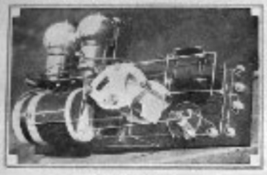
1944AprPS1Eighty years ago this month, the April 1939 issue of Popular Science showed how to put together this simple one-tube regenerative receiver.

The set employed a 25A7GT tube, which combined rectifier and pentode. The article noted that the set had a range of about a thousand miles on the broadcast band, but the parts list called for “a set” of plug-in coils. So there’s no reason why the set, with appropriate coils, couldn’t pull in shortwave signals.

The set uses the familiar “curtain burner” line cord to step down the filament voltage. Also, if you’re considering building such a set, there is an important safety reminder. Depending on which direction the line cord is plugged in, there’s a possibility that the chassis is hot. Even if you use a polarized cord to make sure the chassis is neutral, then the rectified line voltage is hooked directly to the headphones. So if you plan to recreate this particular set, please use extreme caution.

1944AprPSschematic