Category Archives: Radio history

Postwar Radio Sales Begin

1945SepRadioRetailingSeventy-five years ago this month, the September 1945 issue of Radio Retailing was a thick one–175 pages. It was packed with ads from radio suppliers announcing that new radio would be rolling off the assembly lines for the first time in over three years. There was a pent up demand, and it was going to be a great time to be a radio dealer.

This editorial from that issue of the magazine tells all about the great day that was finally there. It was going to be a prosperous time, as Americans hit the showrooms for radios, appliances, and even television.

From most browsers, you can click on the image above to view it, and then click again for an enlarged version.


1940 Portable

1940AugPS3Europe may have been at war 80 years ago, but it was still peacetime in America, and this happy couple was enjoying a radio program while on the go, thanks to this new portable receiver, said to resemble a camera. The manufacturer is not named, but it’s shown in the August 1940 issue of Popular Science.

The set resembled a camera in its outward appearance, and was available with either a carrying strap or handle. It weighed in at 4.5 pounds, and measured 4 by 5 by 8 inches. It employed miniature tubes, and used normal flashlight batteries for the “A” battery. The superheterodyne receiver featured a built-in aerial and dynamic speaker. It also had a connection for headphones for private listening or pulling in distant stations.


1945 FM Phono Oscillator

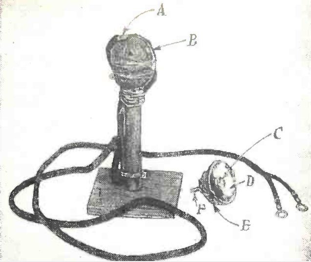
1945AugPM21945AugPM3The woman shown above, in the August 1945 issue of Popular Mechanics, appears to be tuning in a program on her broadcast radio. But looks are deceiving, and the set actually tunes the prewar FM band, which covered 42-49 MHz.  And she’s not listening to a radio station.  Instead, she’s listening to a record being played by the gentleman at left, who is a few feet away.

Phono oscillators which played records over a standard AM broadcast radio were fairly common, but this one played the records over an FM radio. According to the article, no claim was made that the simple circuit would give absolutely perfect reproduction, but results from the Popular Mechanics laboratory were satisfactory. The set was more a challenge to the experimenter to open up the new field of FM radio.

The whole circuit was remarkably compact, and consisted of a 6C5 triode tube along with a few other components. Even with wartime parts shortages, most of the parts could probably be scrounged up fairly easily. The whole circuit mounted right on the tone arm, which was constructed of hardwood.

1945AugPM4


1970 Soviet 8 Transistor Portable

1970AugYoungTechnician2

Fifty years ago, if a young Soviet comrade were ambitious, and perhaps had a better than average access to parts, he or she would be rewarded with this handsome 8 transistor superheterodyne radio that covered longwave, medium wave, and shortwave broadcast bands.

The plans appeared fifty years ago this month in the August 1970 issue of
Юный техник (Young Technician) magazine.

1970AugYoungTechnician

1970AugYoungTechnician3


1960 British 5 Tube P.A. Amplifier

1960AugPracWirelessCoverSixty years ago this month, the August 1960 issue of the British Practical Wireless magazine carried the plans for this handsome five-tube public address amplifier. The guiding principles behind the design were reliability, portability, and economy. It put out 10-12 watts at modest cost and weight. The built-in speaker was said to provide for dance music in a medium size hall, and in the open air, with reliable speakers, speech would be intelligible about 500 yards.

1960AugPracWirelessSchematic


1940 Portables

1940AugRadioRetailingEighty years ago, this couple couldn’t decide which portable set they were going to take to the beach, so they decided to take them all. The sets shown originated with RCA Victor, Automatic, Emerson, Sonora, Majestic, and Philco. The picture appeared on the cover of the August 1940 issue of Radio Retailing.


1970 Carrier-Current Remote Speaker

1970AugPMFifty years ago this month, the August 1970 issue of Popular Mechanics showed how to put together this somewhat ambitious project, a remote carrier-current speaker for your hi fi. A one-transistor transmitter was hooked to the output of your amplifier, and the receiver could be plugged in to any outlet in the house to listen remotely. The project also gave you an easy method of having an outdoor speaker, as long as you had an outdoor outlet. If desired, you could construct additional receivers for use in other rooms, all tuned in to the same transmitter. The speakers were equipped with individual volume controls.

To simplify the project, the receiver used a pre-wired audio amplifier available from Lafayette Electronics. The electronics all mounted in a small box that could be affixed to the back of the speaker.

Both transmitter and receiver used a standard 455 kHz IF transformer for their tuned circuit. These were tweaked to get them down to about 400 kHz, the frequency used by the system. That signal was transmitted through the power wiring. This “antenna” was coupled to the circuit on both ends through capacitors.

Transmitter schematic.

Transmitter schematic.

Receiver schematic.

Receiver schematic.


Emergency Hospital Antennas, 1945

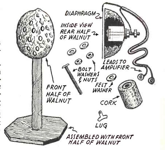
1945AugPM5I was a little unclear on the concept when I first saw this illustration in the August 1945 issue of Popular Mechanics, and I suspect that whoever wrote the caption might have been similarly confused.

The caption is “emergency antenna for individual hospital patients,” and is then followed by some details for each of the illustrations. I believe that what they really mean to say was that these were four different ideas for emergency antennas.

I guess I was confused because of the picture on the left. It appears that these wires are to be attached to the antenna terminal of the radio. I was confused because a similar idea, wrapping the radio with wire, can be used to connect an antenna to an external antenna, even though the set doesn’t have an antenna connection. The loop of wire couples inductively to the internal antenna coil. But in this case, the coil of wire apparently is the antenna.

Figure 2 is simply a loop of wire wound around a piece of cardboard and, again, hooked to the radio’s antenna connection. Figure 1 is the same antenna, but cleverly concealed behind a photograph. Figure 4 looks like a lot of work, since it consists of a spider web coil hidden inside the speaker.

It seems to me that a more suitable solution would be to toss a length of wire out the window when the nurse wasn’t looking, although she seems to be very watchful.