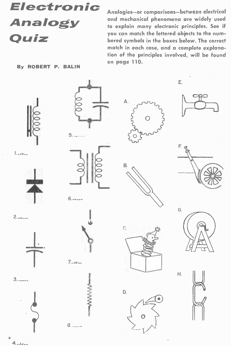
 Today’s quiz first appeared sixty years ago this month in the August 1960 issue of Popular Electronics. We’ll post the answer tomorrow.
Today’s quiz first appeared sixty years ago this month in the August 1960 issue of Popular Electronics. We’ll post the answer tomorrow.
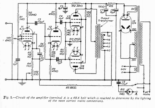
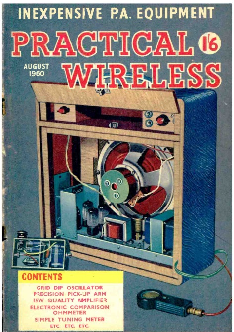 Sixty years ago this month, the August 1960 issue of the British Practical Wireless magazine carried the plans for this handsome five-tube public address amplifier. The guiding principles behind the design were reliability, portability, and economy. It put out 10-12 watts at modest cost and weight. The built-in speaker was said to provide for dance music in a medium size hall, and in the open air, with reliable speakers, speech would be intelligible about 500 yards.
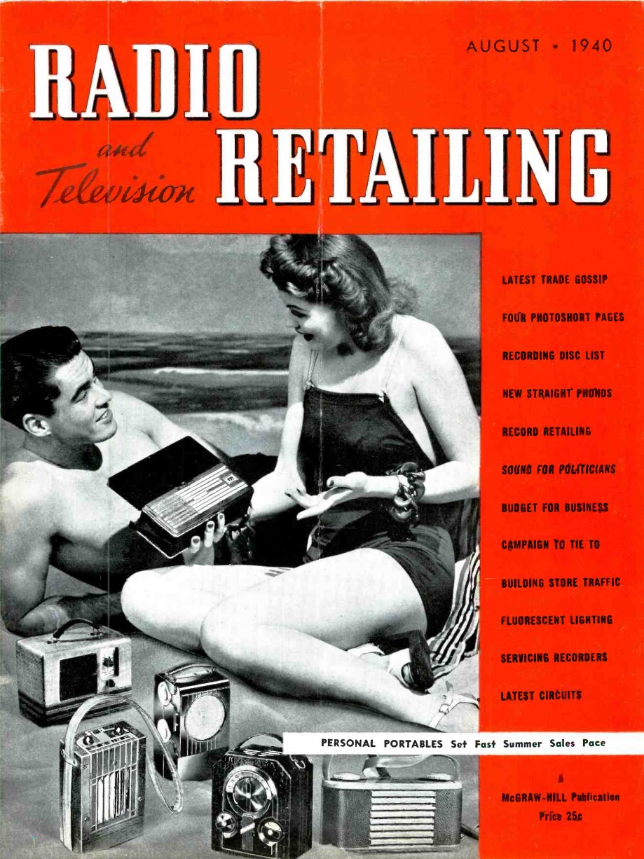 Eighty years ago, this couple couldn’t decide which portable set they were going to take to the beach, so they decided to take them all. The sets shown originated with RCA Victor, Automatic, Emerson, Sonora, Majestic, and Philco. The picture appeared on the cover of the August 1940 issue of Radio Retailing.
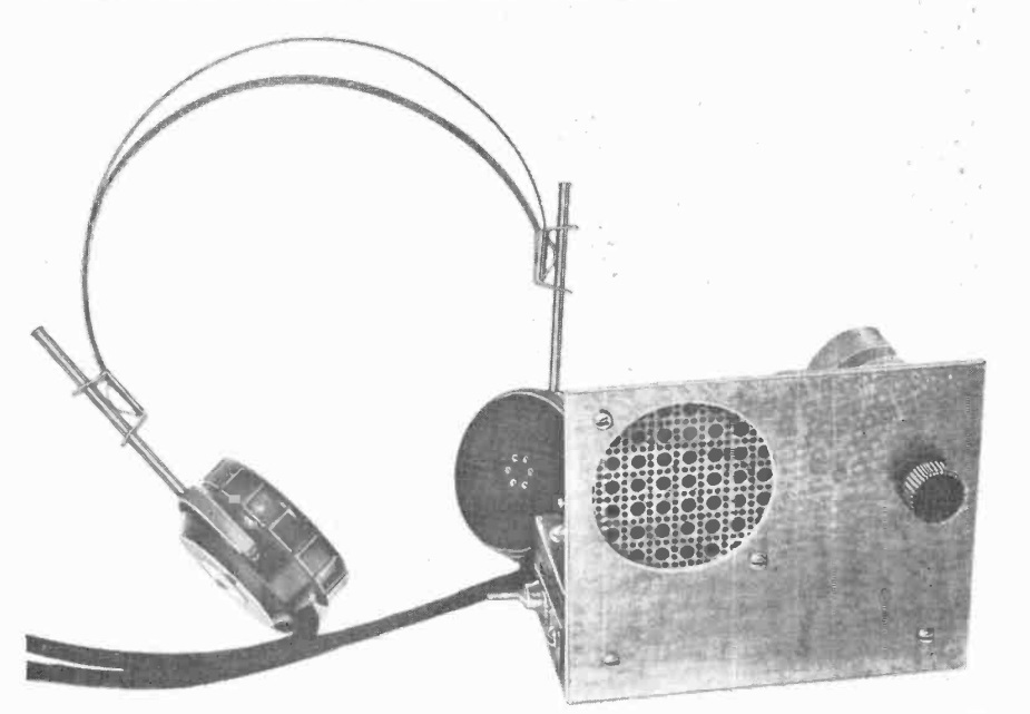
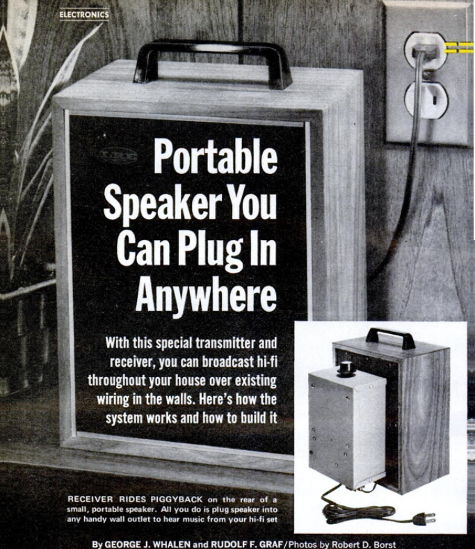 Fifty years ago this month, the August 1970 issue of Popular Mechanics showed how to put together this somewhat ambitious project, a remote carrier-current speaker for your hi fi. A one-transistor transmitter was hooked to the output of your amplifier, and the receiver could be plugged in to any outlet in the house to listen remotely. The project also gave you an easy method of having an outdoor speaker, as long as you had an outdoor outlet. If desired, you could construct additional receivers for use in other rooms, all tuned in to the same transmitter. The speakers were equipped with individual volume controls.
To simplify the project, the receiver used a pre-wired audio amplifier available from Lafayette Electronics. The electronics all mounted in a small box that could be affixed to the back of the speaker.
Both transmitter and receiver used a standard 455 kHz IF transformer for their tuned circuit. These were tweaked to get them down to about 400 kHz, the frequency used by the system. That signal was transmitted through the power wiring. This “antenna” was coupled to the circuit on both ends through capacitors.
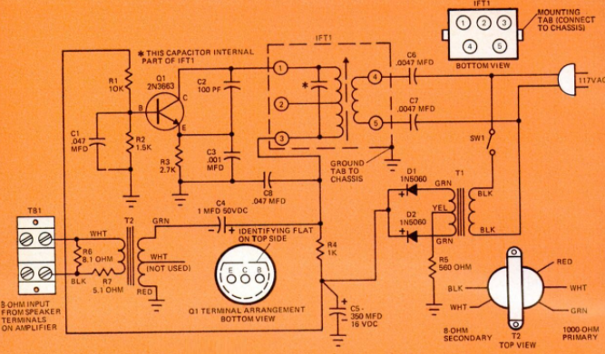
Transmitter schematic.
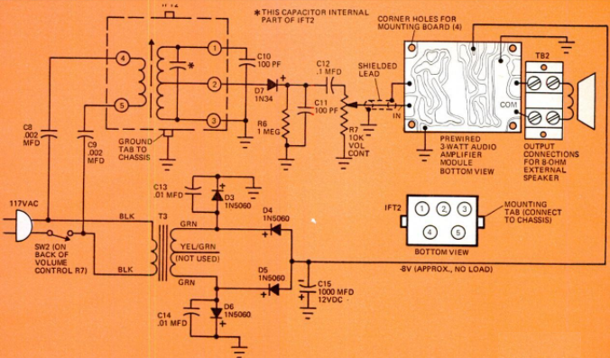
Receiver schematic.
 I was a little unclear on the concept when I first saw this illustration in the August 1945 issue of Popular Mechanics, and I suspect that whoever wrote the caption might have been similarly confused.
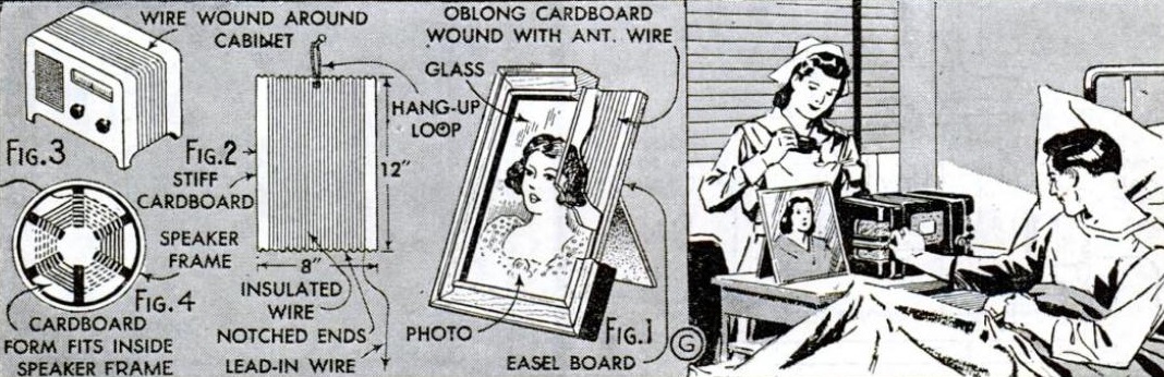
The caption is “emergency antenna for individual hospital patients,” and is then followed by some details for each of the illustrations. I believe that what they really mean to say was that these were four different ideas for emergency antennas.
I guess I was confused because of the picture on the left. It appears that these wires are to be attached to the antenna terminal of the radio. I was confused because a similar idea, wrapping the radio with wire, can be used to connect an antenna to an external antenna, even though the set doesn’t have an antenna connection. The loop of wire couples inductively to the internal antenna coil. But in this case, the coil of wire apparently is the antenna.
Figure 2 is simply a loop of wire wound around a piece of cardboard and, again, hooked to the radio’s antenna connection. Figure 1 is the same antenna, but cleverly concealed behind a photograph. Figure 4 looks like a lot of work, since it consists of a spider web coil hidden inside the speaker.
It seems to me that a more suitable solution would be to toss a length of wire out the window when the nurse wasn’t looking, although she seems to be very watchful.
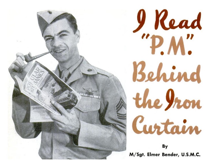
 Our readers enjoy perusing old issues of Popular Mechanics and other magazines, so we understand the excitement of U.S. Marine M/Sgt. Elmer C. Bender in finding the magazine’s August 1947 issue. The flyer, stationed at Tsingtao, China, took off the morning of October 1948 to get in some hours in a training flight.
Due to a faulty fuel gauge, he and Navy Electrician’s Mate William C. Smith were forced to land on a beach only 15 miles from their base, where they were quickly surrounded by Chinese Communists who surmised that they were spies. They were held for over a year until their eventual release.
The two men reported that they weren’t mistreated, but were taken from village to village. Their main problem was boredom, but the Lieutenant charged with their custody would occasionally bring English reading material. The highlight of their stay was when he showed up with the magazine, which both men devoured. Bender reports, in the magazine’s August 1950 issue, that he was especially interested in the issue’s feature on how to solder. When the men were eventually released, the Communist Lieutenant, noting their enthusiasm for the magazine, asked them to send him some more copies upon their return to the U.S.
 While there’s no evidence that either man became a ham, it’s likely that they passed many hours reading about the 5-band AM-CW transmitter shown here. When their families got an FM radio, they probably both instinctively knew the trick of placing a folded dipole antenna under a carpet, as shown in the magazine.
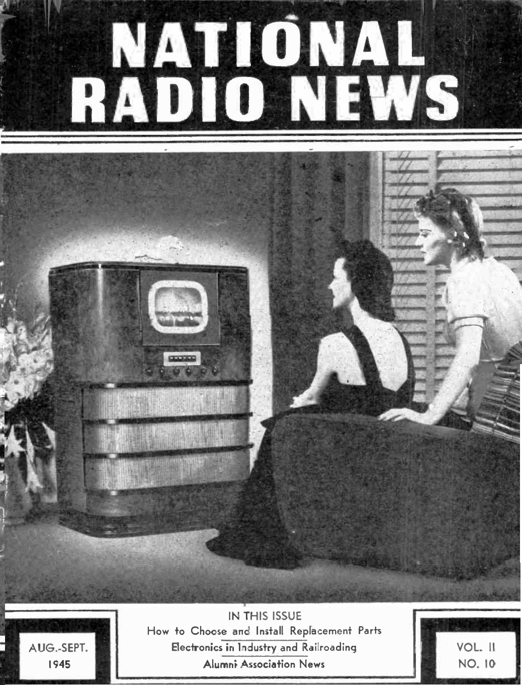 When this issue of National Radio News, August-September 1945, went to press, the war was still raging in the Pacific. But the end was in sight, and despite the cynicism of skeptics, the editors of the magazine knew that television’s role in the postwar electronic era was a foregone conclusion, “witness the rapt attention of these comely lasses as they view the screen of the General Electric receiver.”
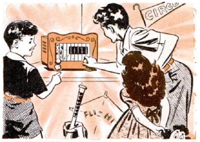
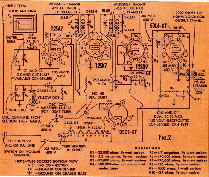
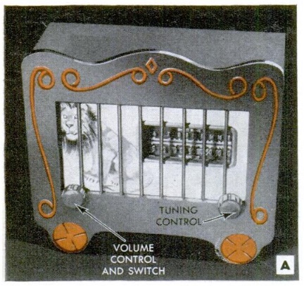 These lucky youngsters have probably been drawing Social Security for about a decade, but in 1950, they were tuning in a favorite program on this attractive five-tube radio put together by their dad and big brother. The internal circuitry was a typical “All American Five” superhet, with a tube lineup of 12SA7, 12SK7, 12SQ7, 50L6, and 35Z5 rectifier. Since this was an AC-DC set, the article cautioned that the screws holding the chassis to the wooden case should be covered up for safety.
The cabinet is designed to resemble a circus wagon. The front is carefully painted with red and white enamel paint, with wooden dowels making the cage. Then, after the paint has dried, animal decals are applied.
The plans appeared in the August 1950 issue of Popular Mechanics.
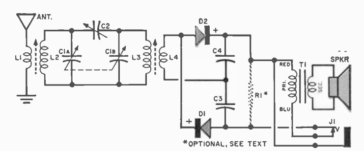
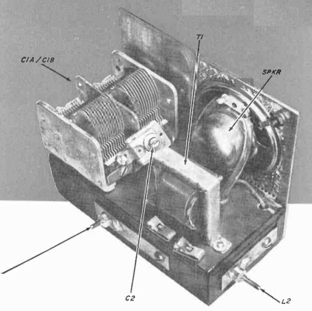 Sixty years ago this month, the August 1960 issue of Popular Electronics showed how to make the holy grail of crystal sets: a crystal set capable of loudspeaker operation.
The author, Walter B. Ford, reported good reception, including loudspeaker volume on strong local stations. The set relied upon two secrets. First of all, it had two tuned circuits in the front end for maximum selectivity. It also used two 1N34A diodes in a voltage-doubling circuit. For weaker stations, headphones could be used, or it could be used as an excellent AM tuner for an external amplifier. But for the strong stations, it would drive the speaker, with no power source other than the received signal.
The ferrite loopsticks might be hard to find these days, although with a ferrite rod, you should be able to make your own. More information can be found at this link. More hints on sourcing the parts can be found at my crystal set parts page.
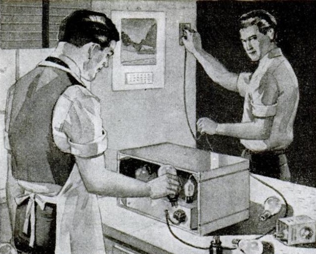 This photo isn’t as sinister as it looks, and nothing untoward is going to happen to the gentleman at the left. The photo is from the August 1945 issue of Popular Mechanics, and these gentlemen are dealing with wartime parts shortages. They’re doing an emergency repair on this set, and need some way to power the filaments of the six-volt tubes. The filament transformer they need is a wartime priority item, so they instead wired the filaments in series and used a 40-watt light bulb as a dropping resistor.
The picture is accompanied by a table showing the resistance of common lamps.