Category Archives: Radio history

One Tube Electronic Keyer, 1950

1950OctRadioNews
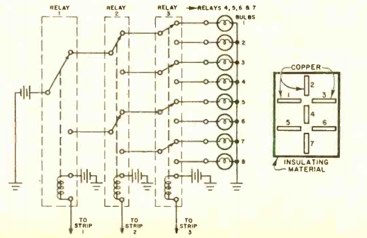
Seventy years ago this month, the October 1950 issue of Radio News carried the plans for this one-tube electronic keyer. The accompanying article describes the circuit in detail, but the reason for two relays is interesting.  The circuit uses a 117L7 tube, half as a rectifier, with the pentode section serving as the relay circuit.  The length of the dots and dashes is determined by the time constant (R times C) of the resistors and capacitors near the key.  Their voltage is fed to the grid of the tube, which turns the plate circuit on and off.

One of the critical design features is that the next dot or dash doesn’t begin until the previous one, and the space following, are finished. The second relay serves this function, as it doesn’t close until the dot or dash is completed.

The author of the article and designer of the circuit was Donovan V. Geppert, W5KFP, an Assistant Professor of Electronics at the University of Arkansas.  He was the author of the textbook Basic Electron Tubes, which is available online at this link.


1950 One Tube Broadcast Portable

1950OctPMThis young woman is listening to a broadcast program on a “handi-talkie” style radio from the October 1950 issue of Popular Mechanics. The set is a simple one-tube regenerative receiver, with a high-impedance headphone built right into the side of the set’s wooden case. A lead with an alligator clip is used to connected to an expedient antenna. In this case, she is pulling in a station by using the lamp’s metal case as an antenna. A telephone dial stop could also be used, or outdoors, a railing or gutter.

Power is supplied by a flashlight battery for the filament, and a 30 volt hearing aid battery for the B+.

1950OctPM2


1940 Three Tube Broadcast Receiver

1940OctPS1940OctPS2This gentleman is pulling in a program on a three-tube set he built for only $4.06, following a design from the October 1940 issue of Popular Science.

The chassis for the set was an aluminum cake pan. The article noted that this had the advantage of being able to be cut with a normal pair of scissors. The handsome cabinet was made from scraps of wood from the author’s workshop. The coils for the regenerative set were made “honeycomb” style on cardboard forms. The set covered the broadcast band, but the author noted that by tweaking the size of the coils, it would be possible to pick up stations slightly above and below the standard broadcast range.1940OctPScoils

The efficient circuit provided loudspeaker volume, driving a PM speaker.

1940OctPSschematic


GE Model JB-410 Portable, 1940

1940OctRadioTodayThis young woman is pulling in a program on her new personal portable radio, the GE model JB-410.  The set weighed in at just 4-1/2 pounds and sold for $19.95. The photo appeared eighty years ago this month in the October 1940 issue of Radio Today.

The superheterodyne set featured a tube lineup of 1R5, 1T4, 1S5, and 1S4, and ran from a 67.5 volt B battery and two 1.5 volt A batteries. There is an example of the set in the collections of the Smithsonian.  There is no photograph available, but presumably if enough people click on the link and then click the button to request a photo, the museum staff will oblige.


Miss America’s Portable Radio: 1940

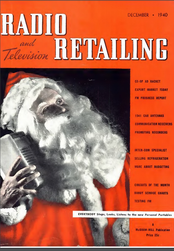
1940OctRadioRetailingShown here is Frances Marie Burke (later, Kenney), Miss America 1940,  tuning in a program from Atlantic City on her portable radio.  The photo appeared in the October 1940 issue of Radio Retailing, which didn’t identify the brand of radio, but reminded that beach portables would be popular the following summer.


October 1, 1940 Eclipse

1940Oct1WashEveStarToday marks the 80th anniversary of the total solar eclipse of October 1, 1940, which was visible in Colombia, Brazil, Venezuela, and South Africa.

One focus of research for this eclipse was its effect upon the ionosphere and radio propagation. As shown from the clipping above (Washington Evening Star, Oct. 1, 1940), scientific teams from the National Geographic Society and Brown University had travelled to Patos, Brazil, and had photographic equipment at the ready. Unfortunately, however, a thick layer of clouds prevented visual study. Other experiments, however, focused on radio propagation and were presumably unaffected by the clouds.

In preparation for the radio studies, the National Bureau of Standards had previously published data regarding normal ionospheric conditions on the date of the eclipse.


1960 Carrier Current Pager

1960SepPESixty years ago this month, the September 1960 issue of Popular Electronics showed how to put together this one-way carrier current intercom. It could be used to listen to the nursery, garage, or other room, anywhere in the house. The transmitter was a simple one-transistor oscillator, using a speaker as the microphone. It sent the signal through the house wiring to another room, where a pickup coil was plugged in and placed near a radio set to a clear spot at the bottom of the dial. Despite the low power, this hookup allowed the signal to be monitored anywhere in the house.

According to the magazine, the parts cost was about $10.

1960SepPE2


1970 Soviet Crystal Sets

1970SepSovietXtalSetIn September 1970, I was probably busy putting together crystal sets. And some things are universal, and it appears that my counterparts behind the Iron Curtain were busy doing just the same thing. These illustrations are from the September 1970 issue of the Soviet publication Юный техник (Young Technician).

Interestingly, my Soviet counterparts were able to buy a suitable inductor, whereas I had to wind mine on a toilet paper tube. I suppose toilet paper shortages might be the logical explanation. In any event, the Soviet kids were able to pull in their strong local stations, just like I could.

The other illustration below isn’t too different from some of my experiments.  From the bottom figure, it appears that the Soviet kids figured out, as I did, that if you used two wires from a transistor, that would work about the same as a diode.

1970SepSovietXtalSet2


1980 Metal Detector

1980SepEEThis young woman is seeking her fortune with a metal detector she put together herself, according to plans contained in the September-October 1980 issue of Elementary Electronics (which had recently merged with Science & Electronics, as noted on her shirt). The article mentioned that the biggest downside of the treasure hunting hobby was the amount of money needed for the equipment, which often exceeded the value of the treasure. But this inexpensive circuit, which could run for a year on a single 9 volt battery, was a good tradeoff between economy and sensitivity. The set was able to locate a penny buried 3-5 inches deep.

The circuit included three inductance coils, two of which were balanced to have a net current of zero passing through them. When a piece of metal came within the field, the inductance of one coil changed, causing the circuit to oscillate. The circuit consisted mostly of an integrated circuit audio amplifier which was wired up to oscillate when the inductance was just right.

The article cautioned treasure hunters that practice was the key, and they should see how the instrument reacts to various pieces of treasure given local soil conditions.

1980SepEE2


1940 Two Tube Regen

1940SepPSgThe young man shown above is now close to being a centenarian, but 80 years ago, he was buying some radio parts from his friendly local radio dealer. He was going to get his money’s worth out of those parts, since he planned to re-use all of them in several different projects, the first of which appeared in the September 1940 issue of Popular Science.

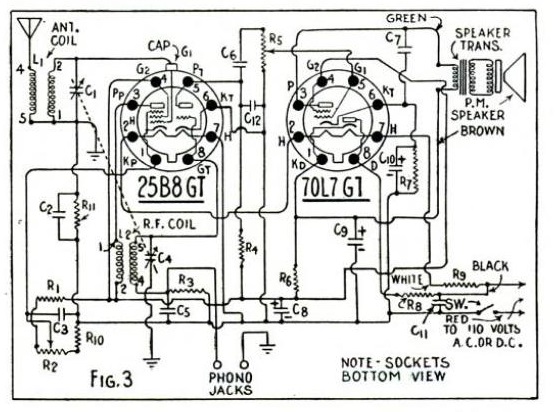
1940SepPShThe total expenditure for all of the projects would be $8.95, and this month, he was purchasing a number of components, including two tubes, a pentode-triode 25B8GT and a pentode-rectifier 70L7GT. This month, he was going to make the two-tube receiver shown below. This month, only one half of each tube would be used. The 70L7GT served as rectifier, and the pentode section of the 25B8GT was regenerative detector. In future months, the circuit would become more elaborate.

The article noted that the capacitors could be soldered in place, but since the resistors would need to be moved around, it was best to attach them using clips so that the leads would be preserved.

The parts list reveals that this version of the set would tune 100-570 meters, meaning that it would cover the standard broadcast band, plus a few interesting signals higher in frequency.

1940SepPSi