Eighty-five years ago, the cover of the April 1933 issue of Popular Science shows cameraman Arpad Kirner being lowered by a fireproof rope 800 feet into the mouth of an active volcano in Italy. He explained that while his colleagues contented themselves on looking down into the volcano, he was able to view phenomena unseen by any human before.
Accompanied by friends (selected for strength to work the winches), he went down and studied the walls with an electric light powered by a wire running alongside the rope.
Of course, it is quite apparent that this stunt was dangerous and should never be repeated. This, of course, is because both the rope and parts of Kirner’s suit were made of deadly asbestos.
Despite the danger posed by the asbestos, Kirner was lucky and lived to the ripe old age of 78, as documented by his grave in Slovakia.
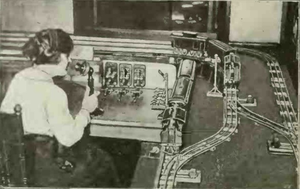
A century ago, with much of the labor force off to war, American industry turned to women to fill many jobs traditionally held by their male counterparts. Shown here is one of the hundreds of young women being trained to be train dispatchers. The article, in the April 1918 issue of Electrical Experimenter, pointed out that the job was exacting, and in the real world, mistakes could easily mean death or dismemberment. Therefore, the women were trained on the model railroad shown here, before being unleashed on the real rails. The dispatcher would set signals and switches, with the model trains responding.
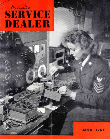
Shown here on the cover of the April 1943 issue of Radio Service Dealer is a SPARS Radioman, a member of the female branch of the Coast Guard. The magazine noted that women were relieving trained radiomen for combat duty, and in the process earning ratings and regular Coast Guard pay and training.
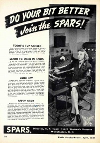
A recruiting ad in the same issue encourages women ages 20-36 to “get into a trim uniform” and put the country one step closer to victory. Those with two years college work and experience were eligible to apply at once for an officer’s commission.
This avid shortwave listener is pulling in a program on her Philips Adagio 52, model BA-511A. The six-tube Austrian set from 1951 covered longwave, medium wave, and two shortwave bands. One of the bands covered 15-51 meters. The second band featured a bandspread to separate stations on the crowded 31 meter band.
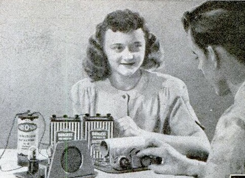
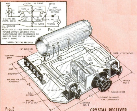
The young man shown here earned his girl’s admiring gaze by putting together two companion projects shown in the April 1948 issue of Popular Mechanics. The first was a relatively modest crystal set featuring a tapped coil, capable of pulling in the local stations with suitable antenna and ground connections.
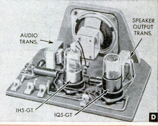
But what really impressed her was the loudspeaker volume achieved with the audio amplifier using a 1H5GT and 1Q5GT tube to drive the 3″ speaker handsomely mounted on the front panel. The crystal set, of course, needed no power source. The amplifier ran from a 1-1/2 volt dry cell and two 45 volt batteries in series.
In addition to working well with the crystal set, the amplifier could be used with a crystal phono pickup or other electronic projects.
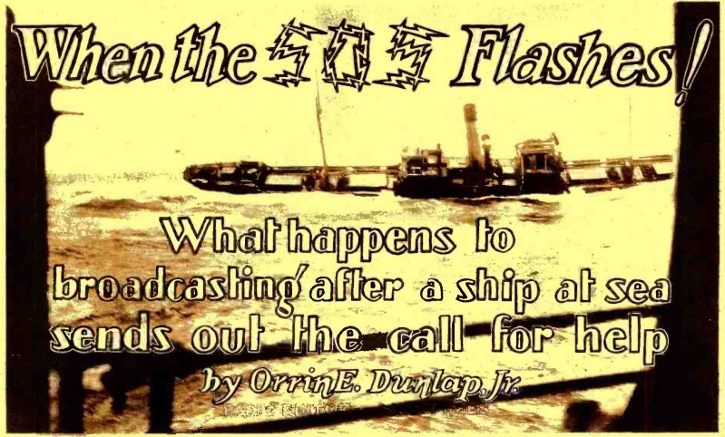
Ninety years ago this month, the April 1928 issue of Radio News carried this article explaining some of what happened when an SOS was heard on the airwaves.
As soon as an SOS was heard, coastal stations WNY in Brooklyn or NAH at the Brooklyn Navy Yard would immediately flash the message “QST DE NAH QRT SOS,” meaning that all stations–including broadcasters–along the Eastern Seaboard would need to immediately silence their transmitters. Network programs would continue over the wire to stations further west, but the key stations themselves would be silent. As the article pointed out, this sometimes led listeners who tuned in late to think something was wrong with their receivers. But for the radio buffs, this added some opportunities.
First of all, with all of the New York stations dark, listeners in that city had some DX opportunities. Stations such as KDKA and those further west would still be on the air.
And “broadcast listeners who are able to read the Continental Morse code and the quick flashes of radio abbreviations can often follow the rescue arrangements; for the broadly-tuned signals will penetrate into the upper reaches of the broadcast band.” The article noted that NAH used spark for these transmissions, exactly because the signal covered more bandwidth and thus had a better chance of being picked up. Similarly, under the radio regulations, the ship in distress was allowed to have its “transmitting set adjusted in such a manner as to produce a maximum of radiation irrespective of the amount of interference which may be caused.”
The receiver shown above is the creme de la creme of Soviet radio technology, the P-250, better known simply as “Кит” (kit). This receiver was produced from 1949-1980 for the Soviet Military and government, and its performance appears to rival just about anything produced in the West during that time period.
The set was originally developed for the Soviet armed forces, under the direction of Anton Antonovich Saveliev, to fill the need for a high quality receiver for use on vehicles and ships. It had a number of revisions over the years, and had the designations P-250 for the land forces, and P-670 for the navy. The receiver was a success, and the developers were awarded the Stalin Prize of the second degree in 1950.
The receiver started out strictly for official use, both by the military, as well as the KGB and GRU. The set was the apex of reliability. One example is a 1953 P-670 originally installed in a submarine, where it was used until 1970. It continued service in the coastal service until 1985, with no repairs other than scheduled maintenance.
The original 1949 version was a dual conversion superheterodyne with a tuning range of 1.5 – 25.5 MHz spread over twelve bands. A set-top box was available to extend the tuning range to 35.5 MHz. The tuning scale was customized for each receiver, with the scale printed by a photographic method. The first IF was variable from 1.5 to 3.5 MHz, with a second IF of 215 kHz. Bandwidth was switchable between 1, 3, 6, and 12 kHz. The standard power suppl6y was 127/220 volts, 50 Hz, but other supply options were available.
An improved version, the P-250M, was produced between 1957 and 1969. Among other improvements was greater precision on the tuning scale, with calibrations reduced from 2 kHz to 1 kHz.
The final version, the P-250M2, was produced from 1968 until 1980. The main change was the tube type, as the set moved from metal octal tubes to miniature tubes. A special tropical version was also available.
The set was declassified in 1959, and eventually it became sought after by Soviet amateurs. You can see the receiver in action at this video:
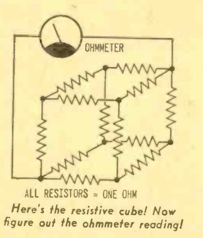
Yesterday, we showed this puzzle from the April-May 1968 issue of Radio TV Experimenter magazine. The question was simple enough–you had to figure out the net resistance between two opposite corners.
Fifty years ago, hobbyists encountering this problem probably started out the way I did, by scribbling the diagram on a piece of paper, trying to flatten it out, and then realizing that the standard equations for series and parallel resistors weren’t really of much help, since they were all hopelessly interlinked.
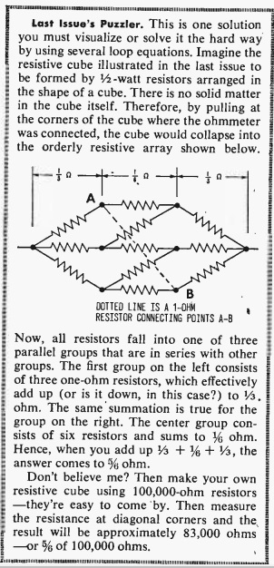
Fifty years ago, the reader had to wait two months for the answer, as shown here in the June-July issue. So I suspect that more than a few got twelve identical resistors, made them into a cube, and then measured.
The key to solving this is to notice that the voltage reading at all three of the points marked “A” is the same. And the voltage reading at all three of the points marked “B” is the same. This is because the diagram is symmetrical, and a current flowing from the left to any of the points A is going to pass through an identical resistance. And a current flowing from the right is going to pass through an identical resistor to get to any of the points B.
Since the voltage reading is the same, we can go ahead and make a direct connection between all of the A points, and another direct connection between all of the B points. Since the voltages are the same, no current will flow, and there will be no effect on the circuit.
The effect that it will have, however, is making the problem a lot easier to solve. At this point, we have three resistors on the left, all in parallel. We have six resistors in the middle, all in parallel. And we have three resistors at the right, all in parallel. It’s easy to compute that the equivalent resistances are 1/3, 1/6, and 1/3 ohm. And those values are in series; so we just add them up, and the answer is 5/6 ohms.
This video takes a slightly different approach to arrive at the same answer:
Today we offer a deceptively simple looking puzzle, taken from the April-May 1968 issue of Radio TV Experimenter magazine.
The question is simple. This cube is made up of 1 ohm resistors on each edge. What’s the net resistance between two opposite corners? The answer will appear here tomorrow.
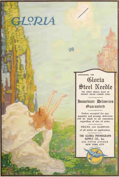
There was a time when phonograph needles were taken seriously, and a century ago was one of those times. This full-page color advertisement appeared in the April 1918 issue of Talking Machine World.

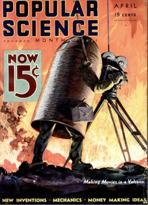 Eighty-five years ago, the cover of the April 1933 issue of Popular Science shows cameraman Arpad Kirner being lowered by a fireproof rope 800 feet into the mouth of an active volcano in Italy. He explained that while his colleagues contented themselves on looking down into the volcano, he was able to view phenomena unseen by any human before.