1956 Code Practice Oscillator

Seventy years ago this month, the February 1956 issue of QST showed this circuit for a very simple code oscillator, using the venerable CK722 transistor. This was actually a simplification of an earlier circuit, which had been updated by George Carson, W0JV.  The oscillator runs on 1.5 volts, but for greater volume, that could be upped to 3 volts.

Carson was a professor at the University of Iowa, and his call is still held by the Iowa City Amateur Radio Club.


1956 British 3 Transistor Portable

Seventy years ago, the British radio enthusiast who wanted to be the first on his block to own a transistor radio could do so, thanks to the plans contained in the February 1956 issue of Radio Constructor.

The portable set, dubbed the “Transistorette,” had been on display at a national radio show, where it had great interest.  As soon as transistors became available in Britain, the editors of the magazine got to work coming up with a practical circuit.  With a short antenna and ground connection, the set provided good loudspeaker volume on the medium wave band.  It was essentially a crystal set, with a three-transistor audio amplifier.  It ran off a 22.5 volt battery, and since transistors were new, the magazine contained a stern warning of the consequences of hooking the battery up with the wrong polarity.


1956 Darb Holiday 3-Way Portable Bike Radio

This cyclist appeared seventy years ago on the cover of the February 1956 issue of Radio Electronics. She is described by the magazine as a “typical Southern university coed,” and she is listening to a favorite program on her Darb Holiday radio, a four-tube portable that could be powered three ways. With separate power packs, it could operate from AC power, 6 volts DC, or dry cells. It featured pushbutton tuning of three preset stations, with no variable tuning.

Another installation by another cyclist is shown at right. The set was manufactured by S.C. Ryan. Co., 1316 Yale Place, Minneapolis.


Prime Number Pencils!

We are pleased to announce the opening of our sister website, PrimeNumberPencil.com!  There, you can buy the perfect gift for the mathematician in your life, the Prime Number Pencil.

The pencil is imprinted with the 24-digit number 357686312646216567629137, which is a prime number. After you sharpen the pencil, it will have the 23-digit number 57686312646216567629137, which is also a prime number. Eventually, it will have the number 37, and then the number 7. No matter how many times you sharpen the pencil, it will be a prime number.

They come in packages of 3, 5, 7, 11, and 23, and shipping is free!

1941 Two Tube Superhet

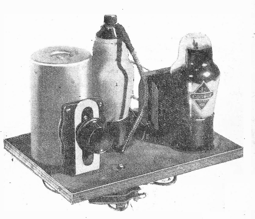
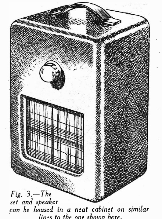
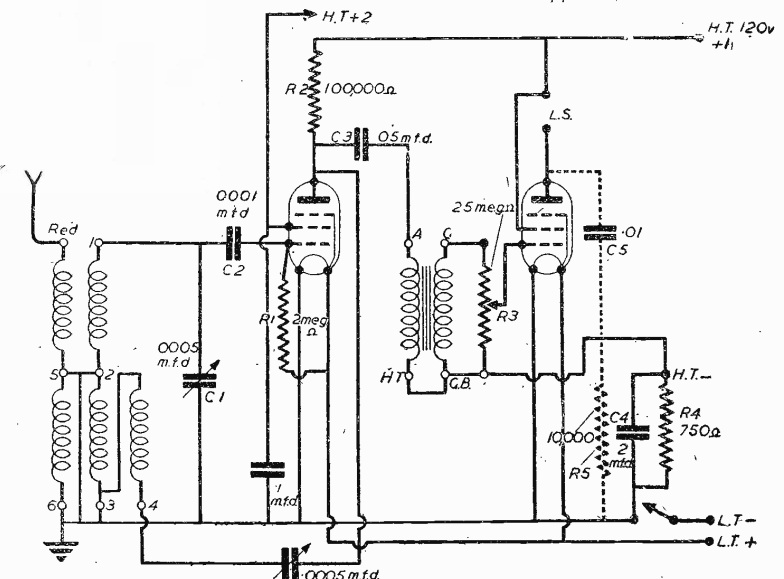
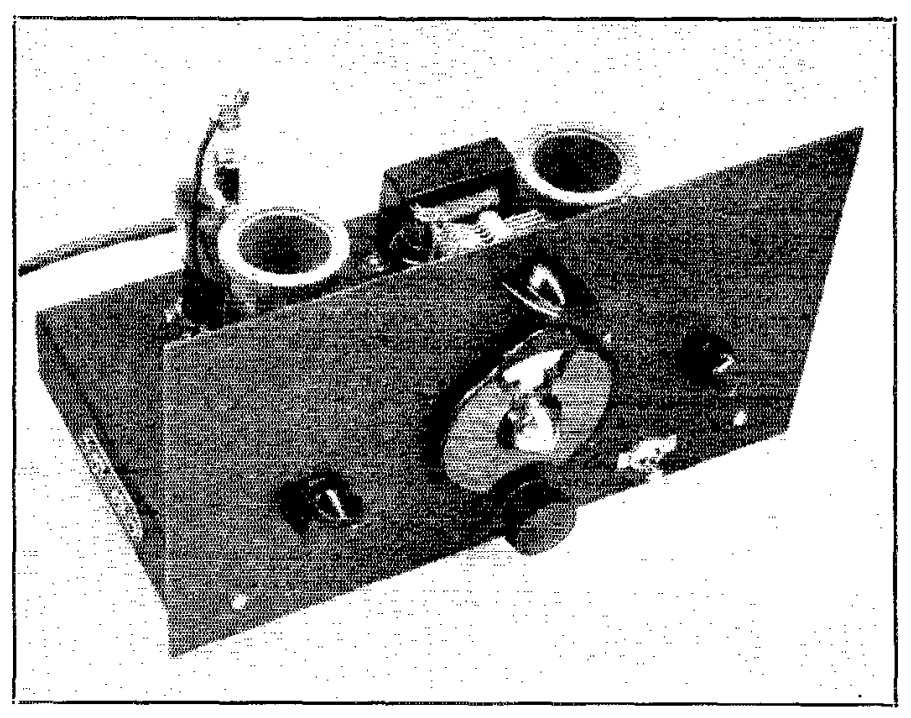
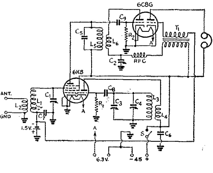
Eighty-five years ago, the February 1941 issue of QST carried the plans for this two-tube receiver which covered 1.4 through 14.5 MHz. The construction article, which carried no byline, noted that it was customary for beginners to start with a two-tube regenerative receiver. This one, however, was a superheterodyne. Since it contained no IF amplifier, the detector stage was actually regenerative.

The article conceded that this seemingly combines the disadvantages of both. But this wasn’t really the case. By having the detector set to a fixed frequency, it could be optimized for stability, particularly because the frequency was low, the set using an IF of about 1600 kHz.

The total cost was $11, $1.50 of which was for the most expensive component, the dial. A 45-volt battery supplied the B+, and a filament transformer was used to provide the 6.3 volts. The article noted that both the battery and the transformer could be had for about $2.


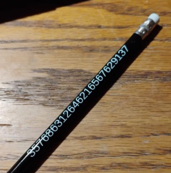
Please visit PrimeNumberPencil.com.
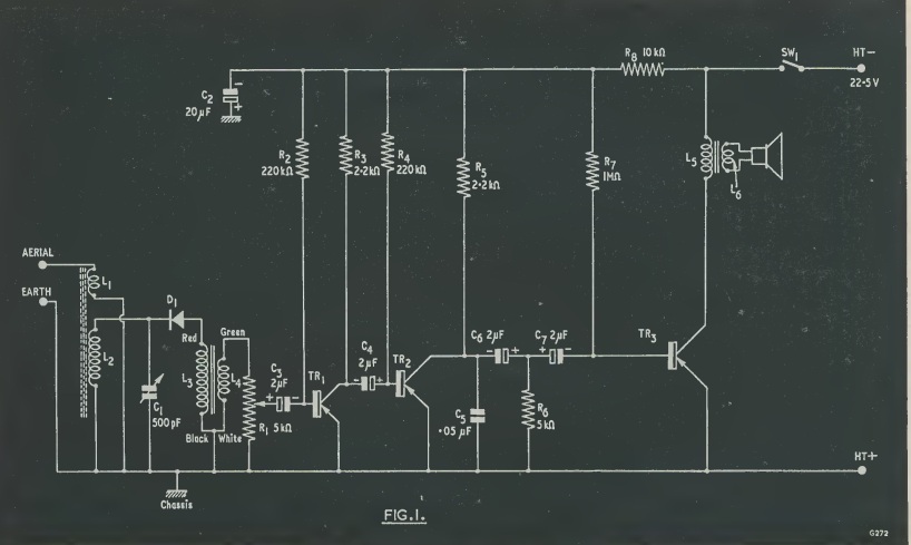
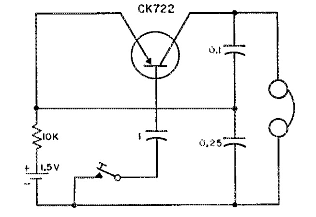
1926 Music Master Model 60

If you were in the market for a radio in Milwaukee a hundred years ago today, you could take home this set from Schuster’s department store for only $69.50, a price which included the set, speaker, batteries, antenna, and tubes. You could be listening right away. The set was a Music Master model 60, and this ad appeared in the February 20, 1926 issue of the Milwaukee Leader.


1941 British Pre-Tuned Two Tube Receiver

Eighty-five years ago this month, the February 1941 issue of Practical Wireless  showed how to build this two-tube receiver . It was specifically designed for use in an air raid shelter from which a reasonable external antenna had been mounted. It could be pre-set to either the Home Service or the Forces program, and once the tuning was set, it needed no further adjustment.

It boasted long battery life for both the filament and high tension batteries. The set could drive a loudspeaker, and the completed project was mounted in the case shown at right.


1946 Philco Radio-Phonos

Eighty years ago today, the February 18, 1946, issue of Life magazine carried this ad for two of Philco’s latest offerings.  The model 1213 was a console radio-phonograph.  The ad mentions that the radio tunes both AM and FM (the new postwar band).  But it also covered 9.3 through 14.5 MHz shortwave.

But the model 1201 was revolutionary, having just been invented by Philco engineers.  There was no more fussing with lids, controls, tone arms, or needles.  You simply inserted the record (of any size), closed the cover, and the record would play itself.


KGEI, 1941

We’ve previously written about KGEI, GE’s shortwave station in San Francisco, and the role it played in World War 2. This item 85 years ago today in the February 17, 1941, issue of Broadcasting shows the transmitter building for the 50,000 watt transmitter that would soon be on the air.

The building is still standing, with the KGEI call letter restored, and is used by Silicon Valley Clean Water.


1926 Experiments in Polarization

The illustration on the cover of QST 100 years ago this month, February 1926, looks fanciful, but it’s a real scene. The accompanying article contains an actual photograph of the structure, used by Dr. Greenleaf W. Pickard (1877-1956) in carrying out experiments on what we would today call the polarization of radio waves.

Dr. Picard discovered that short waves, unlike long waves, do not remain vertical after leaving the transmitter. The structure was located at Seabrook Beach, NH, and analyzed waves of 80, 40, and 20 meters. Most of the stations received were calling CQ on the ham bands, and a number of schedules were also made. A total of 379 stations were logged to gather the data, including a few Canadian and European stations.

The article concluded by requesting readers to submit reports. It cautioned that a mere list of “calls heard” would be of little use. What was needed was comparisons of vertical vs. horizontal receiving antennas.