Category Archives: Radio history

ARRL Fading Tests, 1921

Screen Shot 2021-04-15 at 11.35.14 AM

Don I. Bailey, 9CS.  QST, May 1921.

Don I. Bailey, 9CS. QST, May 1921.

A hundred years ago this month, the May 1921 issue of Popular Mechanics carried a report of the ARRL Fading Tests of 1921.  In collaboration with the U.S. Bureau of Standards, hams took part in a citizen science experiment aimed at understanding the ionosphere.

During the tests, several stations, located in Chicago, Indianapolis, Hartford, New York City, and Washington, sent the letters of the alphabet, forward and backward, while participating stations noted the signal strength. This log was submitted by Don Bailey, 9CS, of Clinton, Iowa.


1951 Remote TV Tuner

1951MayServiceThere was a time when, if you wanted to change the channel on the television, you had to get up and turn the knob on the set. Attempts at overcoming this shortcoming date back to the early days of television. And in 1951, if the entrepreneurial TV serviceman wanted to sell a valuable service to his customers, he could offer a remote tuner such as the one shown here. The May 1951 issue of Service magazine explains everything that needs to be done, and it’s clear that it would be a lot of work.

All of the coils would need to be removed from one unused channel in the set, and replaced with a coaxial cable running to the output of the remote tuner. But it wasn’t quite that simple. The remote tuner would need an antenna input of its own, and it might require a separate preamp. And if the customer wanted to adjust the contrast or volume, that would require additional wiring.

But once done, the customer would be able to change channels from the comfort of his easy chair, a luxury unknown to most people.


1941 Two Tube Regen

1941MayPSThe plans for this unusual looking two-tube receiver appeared in Popular Science 80 years ago this month, May 1941. The controls were mounted on top of the chassis, meaning that the added expense of a front panel was unnecessary.

The set is billed as having two detectors. In reality, a 1N5G tube is used for the detector, with regeneration provide by a 1G4G following it, with that tube’s output being fed back through a tickler coil to the first stage. This made the set very efficient, to the point where it would be able to operate a speaker directly at some locations. The detector could also serve as an audio amplifier, allowing a crystal phonograph pickup to be hooked in as shown in the schematic below. With the appropriate plug-in coil, the set could be used for shortwave.

1941MayPS2


Nestle In Your Daddy’s Arms: 1921

1922MayTalkingMachineWorldA hundred years ago this month, the May 1922 issue of Talking Machine World carried this ad promoting the song “Nestle In Your Daddy’s Arms” from its publisher, Leo. Feist Inc., located in the Feist Building, New York City. Presumably, everyone knew where that was, since the ad didn’t bother giving the address. But for those of us not in the know, it was at 231 W. 40th Street.

The song is performed in this video on Columbia Records by Frank Crumit.  If that name sounds familiar, it’s because we previously profiled his wife, Julia Sanderson, with whom he went on to have a popular radio program.  He’s also famous for his thousands of ukulele recordings.

And here it is on the player piano:

You can hear a Victor recording by a quartet at this Library of Congress link.

Music for band in 23 parts is available at this link, and sheet music for piano is available at this link, where it is revealed that the song was penned by Lou Herscher and Joe Burke. Burke went on to pen “Tiptoe through the Tulips” in 1929 and Rambling Rose in 1948. It’s unclear which
came first, but the sheet music also contains French lyrics, “Repose Mon Enfant sur mon Épaule” written by Jean Nelis.


1951 Regency TV Signal Booster

1951MayRadioRetailing2There was a time when people dressed up to watch television, and 70 years ago was one of those times, as shown by this ad from the May 1951 issue of Radio & Television Retailing magazine. This viewer obviously lived in a fringe area, and the signal wasn’t quite strong enough to produce a good picture. This was solved with the addition of a Regency booster, a preamplifier that went in the line between the antenna and TV.

In particular, the booster appears to be Regency’s model DB-410A.


Two Tube Broadcast Receiver: 1951

1951MayPM

Seventy years ago, this gentleman was pulling in a program on the standard broadcast band with headphones, but in the following months, he would be able to listen to the shortwaves with loudspeaker volume. He is shown here listening to the first iteration of a progressive receiver featured in the May 1951 issue of Popular Mechanics. In coming months, additions would be made to the set to allow shortwave reception and loudspeaker operation.

The set was battery powered, and the magazine pointed out that there were a number of good reasons for putting together a battery set. The most important reason was having a set capable of operation independent of the power lines for civil defense purposes. The circuit was also simpler and saved having to deal with baffling power supply troubles.

This version of the set used a 1U4 tube as regenerative detector followed by a 3V4 audio amplifier. An indoor antenna and ground could be used for local statioms, but an outdoor antenna would be best for long distances. “With a battery-operated emergency receiver of this description, you are not cut off from outside news and vital civil-defense information should local power sources fail. Most of us do not realize how important this could be.” You would, of course, need to keep fresh batteries on hand. The circuit called for flashlight batteries for the filament, and a 45 volt battery supplying the B+.

1951MayPM2


1921: First Radio Fog Signals in NY Harbor

1921May8NewYorkTribuneA hundred years ago today, May 1, 1921, navigation in New York Harbor became a safer proposition thanks to being equipped with a system of radio warning signals aiding navigation. Lighthouses and light ships had long been present, but they were of very limited usefulness in foggy conditions. Therefore, the lighthouse at Sea Girt, NJ, as well as the light ships Ambrose and Fire Island were equipped with powerful radio beacons.

Official notices had been made to mariners, and many vessels were already equipped with radio compasses in the form of a rotatable loop attached to the receiver. The beacon would identify in Morse, and the bearing could be fixed to within one degree.

Radio had been in operation on the Fire Island for some time, as we recounted previously. That ship was equipped with both a wireless transmitter and a bell. By measuring the time between reception of the radio signal and the bell, distance could be accurately measured.  The Sea Girt lighthouse, however, was the first land-based radio fog beacon in the U.S.

This description of the system appeared in the New York Tribune, May 8, 1921.


1941 Harmonica Microphone

Screen Shot 2021-04-05 at 1.42.10 PMEighty years ago, if you needed room filling volume from your Harmonica, there was no need for additional lung power. Instead, you could move up to the next level with electronic amplification, courtesy of this microphone shown in the April 1941 issue of Popular Mechanics. As shown here, your kids will be delighted at the prospect of this musical entertainment.

The microphone was designed to plug into the phono jack of a radio, and up to five could be wired in parallel for your next harmonica quintet performance.  The microphone was also suitable for guitar, violin, piano, and many wind instruments.  It was manufactured by the Amperite Company, then of 561 Broadway, New York.


Radio Repairman, 1941

1941AprNrnEighty years ago, the radio repairman was a heroic figure, as shown by this illustration on the cover of the April-May 1941 issue of National Radio News.  While the lady of the house and faithful canine companion look on, he is getting this set back into operating condition.

Perhaps he had to replace a tube, or perhaps he was resetting the set’s pushbuttons.  This was necessary since the FCC had just changed the frequencies of most U.S. radio stations on March 29, 1941.  An article in the magazine included a timely feature going into detail on the circuits involved.


1921 25 Cent Crystal Set

1921AprRadioNews1
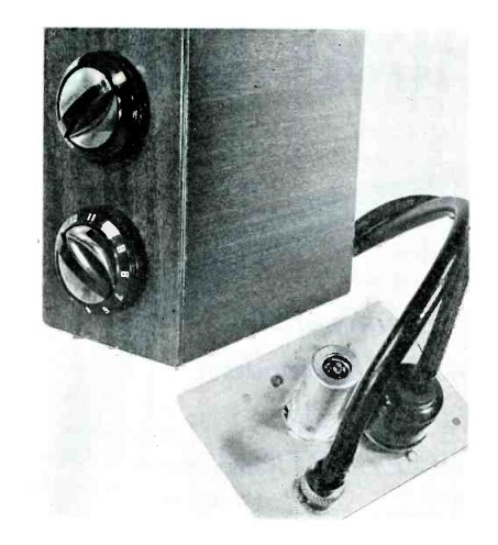
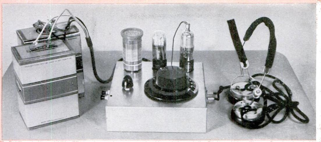
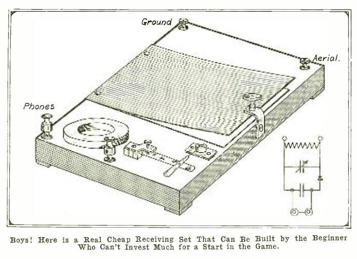
A hundred years ago this month, the April 1921 issue of Radio News showed how to build this simple receiver, said to have a cost of only 25 cents. Tuning was accomplished with a variable capacitor consisting of aluminum plates separated by waxed paper. By compressing the plates, the capacitance was changed.

The magazine lamented that there were probably thousands of lads who looked wistfully at the catalogs, only to be discouraged by the high prices. The thought was that if they got a chance to listen in with this inexpensive set, they would be sold on the idea of radio and would soon figure out a way to put together a more impressive station.

Accroding to the magazine, almost every town had a good amateur station holding court on 200 meters, and receiving them even with this simple crystal set would be a simple matter.

I have no doubt that the parts shown here could be had for a quarter. The problem, however, is that the prospective radio ham would still need a headphone with which to connect the set. Looking through the magazine, the least expensive was $4.50, or about $66 in today’s money, according to this inflation calculator.

Those headphones, of course, would still be good when the listener was bit by the radio bug and upgraded to a better set. But the cost of entry to the hobby was $4.75, and not the 25 cents promised by the magazine.