Category Archives: Radio history

1946 General Electric Radios

1946May20LifeSeventy-five years ago today, the May 20, 1946, issue of Life magazine carried this General Electric ad featuring the company’s postwar sets, and Evelyn Kaye.  The magazine didn’t even need to give her full name–she was just Evelyn and Her Magic Violin, and everyone knew who they were talking about, thanks to her appearance every Sunday night on NBC’s Hour of Charm broadcast. You can see her perform at the video below.

The GE radios featured in the ad were no less magical, with exclusive new features made possible by warborn electronics. In particular, the ad notes that the speaker of the Model 101 contained an alnico magnet, 2-1/2 times more powerful than any other magnet. The set was an “All-American Five,” with the familiar tube lineup of 12SA7, 12SG7, 12SQ7, 50L6GT, and 35Z5GT.

Also featured in the ad are the six-tube model 321, featuring pushbutton tuning, and the model 326 or 327 console, which also tuned shortwave. The model number for the portable shown at the bottom is not shown.


1941 Zenith 6G601 Portable

1941May19LifeEighty years ago today, the May 19, 1941, issue of Life magazine carried this ad for a Zenith portable. While the model number isn’t given, it appears to be model 6G601.  The six-tube set ran from a non-rechargeable battery pack, or from AC power.

The distinguishing feature of the Zetith portable was the Wavemagnet antenna.  This was a loop antenna contained in a cardboard cover that looked like a horseshoe magnet.  It came with suction cups to attach it to the window of a car, train, or building.  The compartment with the antenna also had a storage area for headphones for private listening or for the hard of hearing, although they were an optional extra.

The set retailed for $29.95 with airplane fabric cover, or slightly more for genuine cowhide.  Prices were also slightly higher in the west.  According to this inflation calculator, that works out to the equivalent of $544 in today’s money.

If the set looks familiar, it’s because we’ve featured it previously.

A demonstration of a nicely restored example of this set can be seen in the video below.


6 Meter Transceiver for CD Use: 1951

1951MayQST
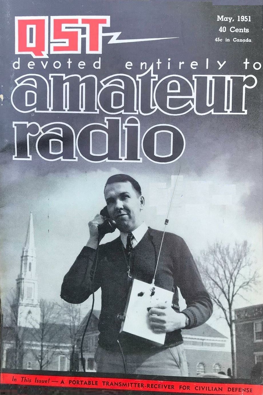
Shown here, on the cover of the May 1951 issue of QST is ARRL’s then-National Emergency Coordinator, George Hart, W1NJM, operating a portable 6 meter civil defense portable station designed by Ed Tilton, W1HDQ and described in the magazine.

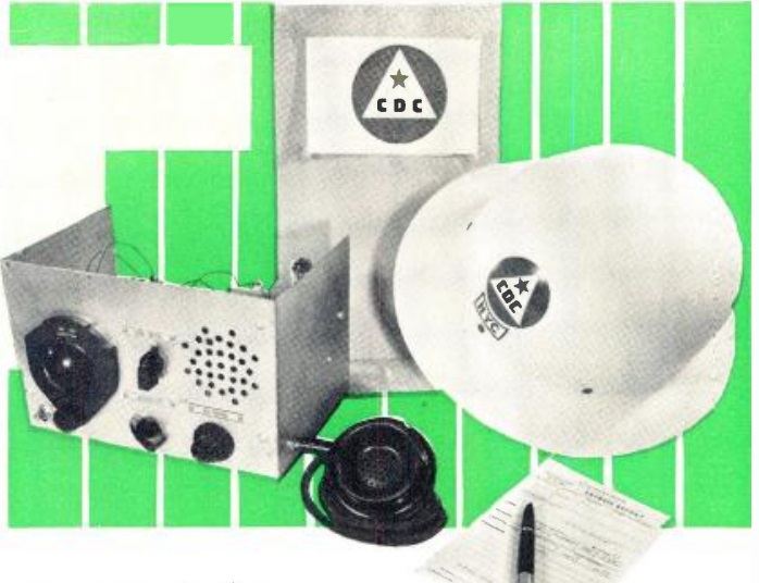
Tilton’s article described the design goals of the set. He noted that in the past, emergency gear almost always meant “rigs with handles,” namely equipment that could be operated on a 6 volt battery or small AC supply. While such rigs were the backbone of WERS during World War II and would continue to occupy a prominent place, the “present emergency” brought a new need, namely, communications for the radiological survey team. Those teams required on-the-spot communications with a transmitter-receiver that could go with an operator on foot, and not tied to a car battery or other power supply.

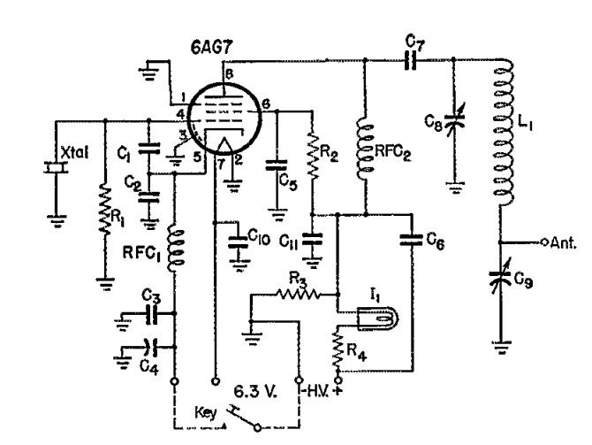
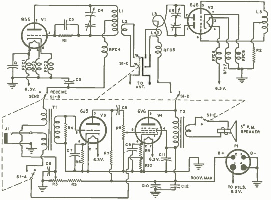
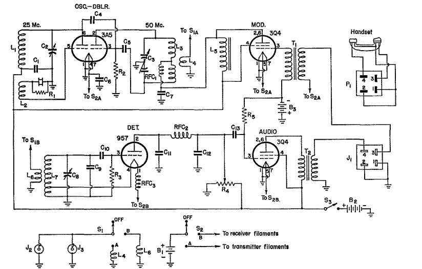
The choice of bands to be used presented some problems. A simple modulated oscillator (such as the one described in another magazine the same month), would eliminate the expense of crystals, but they were really practical only on the 220 MHz band, since the civil defense frequencies assigned on 2 meters were two narrow a range for such a transmitter. On 6 or 10 meters, however, crystal oscillators were more cost effective, and between the two, 6 meters allowed a shorter antenna. Therefore, the choice boiled down to 6 meters, if crystal control was desired, or 220 MHz, if it was not. The circuit shown here was a crystal-controlled transmitter-receiver for six meters.

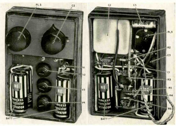
The transmitter used a 3A5 dual triode. The first half was a 25 MHz oscillator using 8.4 MHz crystals on their third overtone, or 25 MHz crystals. The second half of the tube served as a doubler. The set could also be used on 10 meters with different crystals, and using the second half of the tube as an amplifier rather than doubler. A 3Q4 was used for modulator. The superregenerative receiver employed a 957 acorn tube detector, with another 3Q4 serving as audio amplifier.

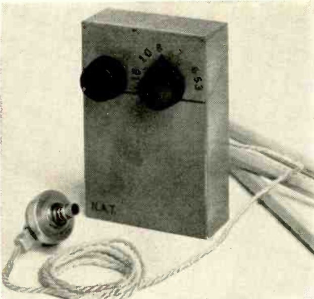
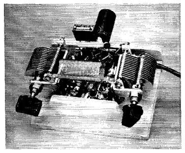
Since the author couldn’t find another suitable carrying strap for the rig, a piece of 300 ohm twin lead was pressed into service.
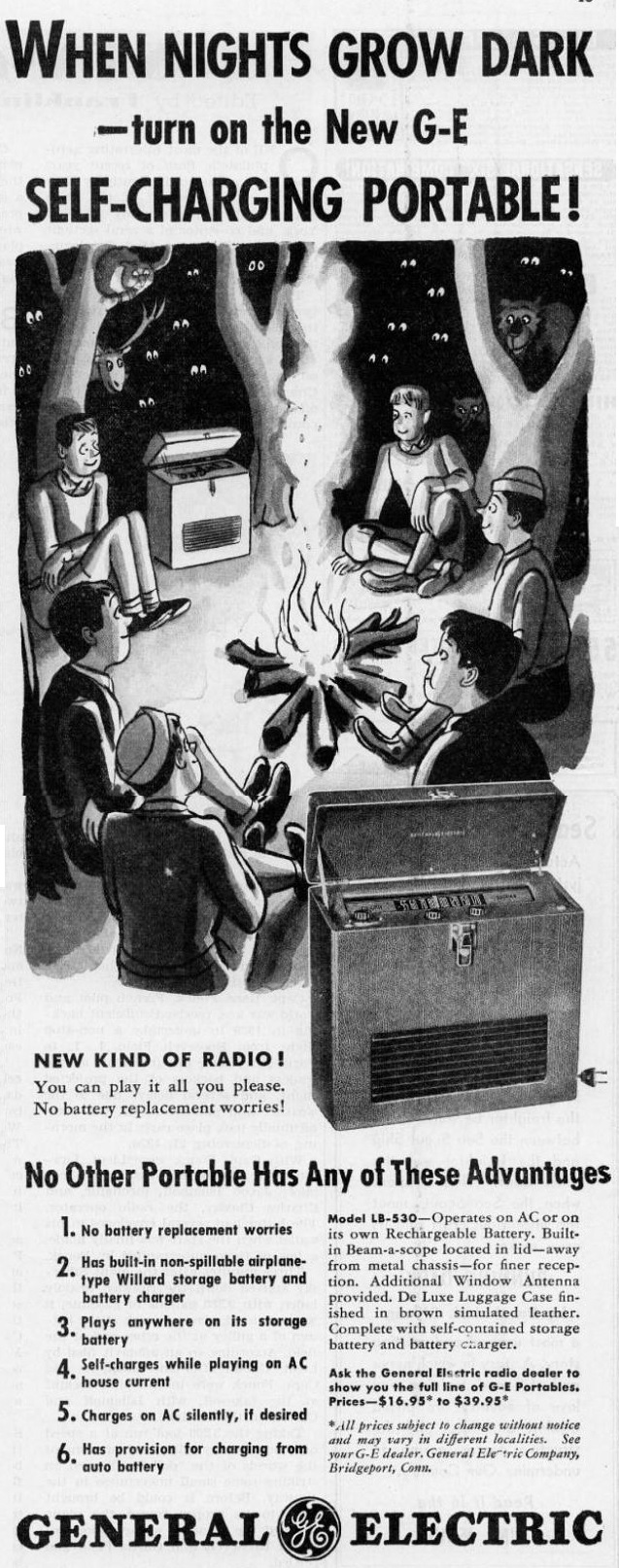
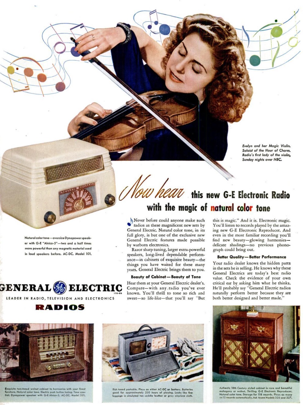
1951MayQST2


1961 Four Transistor Pocket Portable

1961MayRadioElec3z
1961MayRadioElec1Sixty years ago, the May 1961 issue of Radio Electronics showed how to assemble this four-transistor pocket radio. Many items of this era were billed as being “about the size of a pack of cigarettes,” but this one really was. The cabinet was constructed using a cigarette flip top box.

The magazine gave detailed instructions for constructing it. The first step was to carefully cut off the top where it hinges. Various slots were added, and additional cardboard inserts were placed inside for various compartments. At this point, the cardboard box was painted with two coats of Duco household cement, thinned down to a paintlike consistency with laquer thinner or nail-polish remover.  After this was thoroughly dry, you would paint the box with your favorite color enamel and let it try for a few days. The top would be sanded lightly or steel wooled to allow the top to fit back on snugly. The finishing touch was calibrating the dial with the customary markings of 53 through 16 with a “toy printing or rubber-stamp set.” Each number was held with tweezers, coated by a piece of glass with a thin coat of paint, and pressed to the case.

Blueprints for the cardboard cabinet.

Blueprints for the cardboard cabinet.

The chassis could be a standard printed circuit board, and the magazine showed the pattern. Or, another option was to build a circuit board using another piece of cardboard treated with the diluted Duco.

After all that work building the handsome cabinet, you wouldn’t want to skimp on the electronics, and this circuit didn’t. It used a Philco AO-1 transistor as the regenerative detector, along with three of the venerable 2N107 transistors as audio amplifier. The receiver was tested by the publisher, and performed quite well. From the test location 20 miles from New York City, the set was able to pull in nine stations with good earphone volume. It noted that it probably could have heard more stations with careful tuning. The loudest station, which was seven miles away, was loud enough to be heard by two persons with the earphone in a small dish on the table between them.

The author reported similar good results at his location. He noted that it was very selective over the entire broadcast band. He reported at night hearing stations 400 miles away, and three stations 1500 miles away. He also reported that on local stations, he could listen with the earphone six feet away.1961MayRadioElec2


1951 British “Constant Companion”

1951AprRadioConstructorThis utilitarian but handsome receiver graced the cover of the May 1951 issue of the British magazine Radio Constructor. That issue, as well as the June issue, described the circuit and provided details on putting it together. According to the author, the magazine had received numerous requests to design such a set, and those requests asked that the set should be easy to construct, compact, and provide a pleasing symmetrical cabinet.

Those requirements posed a tall order, but with some experimental work, this set, dubbed the “Constant Companion” was the result. The three-tube (including rectifier) circuit tuned the long and medium wave bands, and provided loudspeaker volume with a suitable antenna.

1951AprRadioConstructor2


1951 Crystal Set

1951MayBLSeventy years ago, the May 1951 issue of Boys’ Life carried these plans for “one of the prettiest radios you’ve ever seen.” The chassis was a plastic dinner plate, and the magazine specified that the dish should be yellow, with dashing red fittings. With a good antenna (at least 100 feet) and ground, the set would pull in medium power stations up to 25 miles away.

The coil was wound on a piece of dry wood. As Boys’ Life was sometimes prone to do, they forgot to mention that the enamel insulation would need to be sanded off the wire at the point where the slider contacted it.

If you need help sourcing the parts to recreate this or other crystal set designs, be sure to check out our crystal set parts page.


GE LB-530 Portable, 1941

1941MayBLEighty years ago, these young men, probably scouts, are sitting around the campfire pulling in a distant program, with their General Electric Model LB-530 portable.  The five tube (1A7GT 1N5GT 1N5GT 1H5GT 1Q5GT) set operated off an internal lead-acid battery, which could be charged from either a car or 120 volts, either while playing or when turned off. The two volt internal battery lit the filaments directly, and provided the B+ with a vibrator power supply.

We previously featured another ad for the same set. The set retailed for $39.95. This ad appeared in the May 1941 issue of Boys’ Life.


1951 80 Meter Novice Transmitter

1951MayQST11951MayQST3The Novice Class license was first authorized by the FCC effective July 1, 1951. Actually, July 1 was a Sunday, so the first exams probably took place on July 2, with the licenses arriving several weeks thereafter. Novices were allowed to operate initially on CW on 80 meters (3700-3750 kHz) and on the old 11 meter band (26.96-27.23 MHz), as well as both CW and ‘phone on 2 meters (145-147 MHz). The June 1951 issue of QST carried a feature “How To Pass the Novice Examination,” and included the 28 question study guide for the 20 question multiple-choice test.

The May and June issues also carried the plans for a simple transmitter for the novice to get on the air. The set was designed by ARRL Technical Editor Don Mix, W1TS, who pointed out that a higher power transmitter, or one on the 11 meter band, might require additional shielding or other precautions to avoid television interference. The simple circuit here, however, was capable of contacts even with an antenna as short as five feet, although longer was, of course, recommended. The retail cost of all of the transmitter components was only $15, and the set required only four hand tools to put together: screwdriver, pliers, hand saw, and soldering iron. The chassis consisted of a board, and the tube socket was mounted horizontally on two metal angle pieces.

1951JuneQST1The May issue showed how to put together the transmitter, and the June issue showed an accompanying power supply as well as ideas for an antenna. The author reported that with brief tests from West Hartford, Connecticut, he was able to put stations in Wisconsin and Florida in the log at night, with Maine and Pennsylvania during the day. The set was designed to run to a random wire, and some ideas for the transmitting antenna are shown here. A long outdoor antenna was, of course, recommended, but if necessary, and indoor antenna could be used, and the set would load up into an antenna as short as five feet.


220 MHz Transceiver for CD Use: 1951

1951MayRadioTVNewsSeventy years ago this month, the May 1951 issue of Radio News carried the plans for this 220 MHz transceiver designed for civil defense use. The band was chosen because of it was authorized for use by holders of the newly minted Technician license. With many younger hams being drafted, it was thought that opening up opportunities for Technician class hams would be a way to bring in the operators that were urgently needed for civilian defense operations.

The main design parameter for the set was to provide reliable communications over a 5 mile range. This would be sufficient to cover a small town, or, in the case of a larger city, one police precinct, upon which civil defense operations were often based. Lower bands could be used for inter-city communications, freeing up units such as this for use in local emergencies.

The heart of the circuit was a 955 acorn tube, with more common miniature tubes (6J6, 6J5, and 6V6) rounding up the circuit. The 955 operated as a superregenerative transceiver. The tuned circuit used off the shelf components, but the capacitor required some modification to cover the entire band. If a frequency meter were not available, the magazine noted that in a TV with a 21 MHz IF, the set’s local oscillator would radiate on 225 MHz, allowing calibration of the transceiver. An additional hint in areas with a channel 13 TV signal would be that if the TV station were audible, this meant that the transceiver was tuned too low.

The author reported good signals over a 17-mile path with the set, meaning that for its intended use of 5 miles, the two watt set would likely perform well.

1951MayRadioTVNews2


1941 Sussex, England, SWL Shack

1941MayPracWirEighty years ago, this handsome listening post was located in Sussex, England and was owned by a member of the British Long-Distance Listeners’ Club. Due, undoubtedly, to wartime security needs, the owner was identified only as Member 5490, who had sent the sketch and description for inclusion in the May, 1941, issue of Practical Wireless.

The main receiver was an Eddystone All World Two.  You can read more about that receiver at this link.  The member also had three other homemade receivers as well as amplified speakers. He reported that for light entertainment, he could drive one of the sets with the gramophone pickup and get an output which was quite sufficient for a fair-sized shack. At times when reception was not good, he got quite a bit of fun with home broadcasting, using not only the turntable but the microphone as well.

The member reported that he was waiting for his call up from the Royal Navy as a telegraphist. His normal speed was 32 WPM, but he “managed to take down a couple of pages of French at 42 WPM.” At times, he had managed 53 WPM, but only for one minute.

He reported having 112 QSL cards, covering 83 countries and all continents.