Category Archives: Radio history

Armistice Day Blizzard: 80th Anniversary

Armistice Day Blizzard, Excelsior Blvd., West of Minneapolis.  Minn. Historical Society photo, NOAA.

Armistice Day Blizzard, Excelsior Blvd., West of Minneapolis. Minn. Historical Society photo, NOAA.

Wednesday, Veterans’ Day or Armistice Day, is the 102nd anniversary of the end of World War I. But in Minnesota and the Upper Midwest, it is remembered as the 80th anniversary of the Armistice Day Blizzard of 1940, which was responsible for taking 145 lives. Here are two previous posts about that blizzard:

Newton “Jack” Baker III, 1920

NewtonJackBaker1920Shown here is Newton D. “Jack” Baker, III, the son of U.S. Secretary of War Newton D. Baker.

The picture appeared a hundred years ago this month in the November 1920 issue of Radio News, which reported that he had studied radio telegraphy enthusiastically, and had mounted this portable set on his bicycle, on which he listened while riding around Washington. With just the frame of the bike as an antenna, he was able to pick up NAA Arlington.

1919XmasRadioIf Master Baker and his radio look familiar, that’s because we’ve seen both of them previously. He had been an exceedingly good boy during 1919, and Santa Claus brought the radio as a reward, as shown in this close-up from the picture we previously shared. This photograph is clearly the same boy, the same radio, and even the same headphones as the Christmas photo.

I don’t see any record of Baker having received an amateur license, but it appears that he was an enthusiastic listener in the earliest days of radio.


A Career in Wireless: 1920

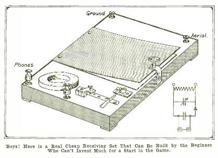
1920NovBLA hundred years ago this month, the November 1920 issue of Boys’ Life asked scouts to ponder the question of whether they should pursue a career in radio.

The article was an excerpt from the merit badge pamphlet for “Wireless Electricity.”  I’ve never run across this name before, but it’s used throughout the article.  According to Wikipedia, Wireless merit badge was discontinued in 1923 and replaced by Radio, and I didn’t find any reference to the name Wireless Electricity.

The article talks about the advantages of a career in radio, such as the possibility of traveling the world as a shipboard radio operator.  It also points out that there was a demand for persons to fill these lucrative positions.  While the article pointed out that there were a number of good schools, it also made clear that most in the profession were self-trained as amateurs, and that this was one of the rare cases where one could get a good job based on such self-education.

The magazine also included some pointers for building a detector, shown at the bottom of the page.


1940 Clock Radio

1940NovPM

The humble clock radio hit the scene shortly after the war, but as we can see from this self-explanatory drawing in the November 1940 issue of Popular Mechanics, one John L. Story of Washington, D.C., had come up with the idea. He mounted a small toggle switch on the back of a wind-up alarm clock not unlike the one shown at left, still available on Amazon.

When this type of clock rings, the key for winding the clock unwinds.  The switch is carefully placed so that the unwinding key trips it, turning on the radio or other small appliance.  For students interested in the history of technology, this would be an interesting science fair project to duplicate Story’s invention and answer the question, “what is the simplest clock radio?”


1940 One Tube Broadcast Receiver

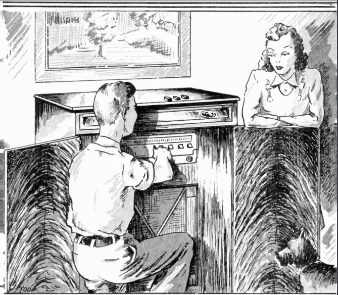
1940NovPS1This young man is pulling in a local station with loudspeaker volume using the circuit shown 80 years ago this month in the November 1940 issue of Popular Science. The set uses a 1E7G dual pentode. One half is an RF amplifier, and the other half serves as the detector, but with enough output to drive a speaker with no further amplification. For stations within ten miles, and indoor antenna can be used, and for local stations further away, a good outdoor antenna is necessary. Selectivity was said to be very good, with the circuit able to separate strong stations only 30 kHz apart.

The set is a TRF, meaning that each stage had its own tuning dial. Two ganged variable capacitors could be used, but the separate dials allow each stage to be tweaked for maximum sensitivity. The 90 volt plate voltage was supplied by two 45 volt B batteries, with a 3 volt A battery lighting up the filaments.

1940NovPS2

1940NovPS3


Halloween Broadcast

1915HalloweenHappy Halloween from OneTubeRadio.com!

For Halloween, I am doing a special broadcast for the neighborhood.  If you discovered this page from that broadcast, welcome to OneTubeRadio.com, a blog covering mostly radio history, but also other eclectic topics.  If you are outside of our broadcast range, you can listen to the full broadcast by clicking the play button below:

Tonight’s broadcast features War of the Worlds, originally broadcast on CBS radio on October 30, 1938.  It also includes Halloween music from French artist Chez Mon Plaisir, who has graciously placed the music in the public domain under a Creative Commons 0 license.  It is available for download at FreeMusicArchive.org.

We are transmitting with our  InfOspot Talking House transmitter, which I previously reviewed at this link.  It is an FCC-certified transmitter for the AM band and operates with 100 milliwatts to a 3-meter antenna.  Tonight, we are broadcasting at 1610 kHz on your AM dial.  It has fairly solid coverage for about two blocks, and in a few spots, can be heard over a mile away.  During COVID-19, I have used this transmitter for drive-in educational programs for my continuing legal education business.  It is also suitable for other socially distanced activities, such as church services and meetings of community organizations.  It could potentially be an important community resource in emergencies.  And tonight, I hope it’s providing some Halloween entertainment to the neighborhood.

Reception reports are welcome.  You can contact us at como-radio@usa.net.

1960 Two Tube Longwave Receiver

1960RadioTVExp3The plans for this handsome two-tube long wave receiver appeared in the Fall 1960 issue of Radio-TV Experimenter.

The AC-DC set used two dual tubes. The two halves of the 6AN8 served as RF amplifier and regenerative detector. Half the 6AU8 was used as audio amplifier, with the triode section pressed into service as rectifier. The set covered 85-550 kHz, and with modification (addition of a coil) could be pressed into service on the broadcast band.

The article addressed the kinds of signals that could be heard on the long waves. At the time, they included the old A-N aviation beacons we’ve previously described.

1960RadioTVExp4


1945 Walnut Microphone

1940OctRadioCraft3We’ve previously shown ideas for homemade microphones, but unlike this one from75 years ago, none of them were made out of a walnut.

This one, from the October 1945 issue of Radio Craft is, indeed, housed inside a walnut. In addition to the large walnut shell, the required components are “a cord, a little cotton batting, a piece of tinfoil, and a few odds and ends.” The heart of the condenser mike is a diaphragm made of thin copper or tin foil, specifically, “the stiff kind, such as used to be used on cards of buttons.”

The foil is stretched carefully over one half of the shell. Through the other half of the shell a cork is inserted, and a brass screw passes through to a washer which is held in place just next to the foil. The article includes a circuit for a preamplifier. The author notes that the completed microphone “needs plenty of amplification, but the quality is as good as that of any commercial microphone I have ever heard.”

1940OctRadioCraft2


Students Tour Winnipeg Radio Station, 1940

1940OctManitobaCallingEighty years ago this month, these students toured the facilities of CKY radio in Winnipeg.  The photo appeared in the October 1940 issue of Manitoba Calling,
the station’s program guide. The students were from the Riverbend School, and were being given a tour of the station by Mr. A. McLean, the station’s official guide. According to the magazine, great numbers of attentive students visited the station. Schools interested in arranging a tour were encouraged to call the station’s public relations department.


1960 One Tube Broadcast Receiver

1960RadioTVExpIf you asked the author of this 1960 article whether he had Prince Albert in a can, he would tell you no, that he let Prince Albert out and instead installed a one tube radio.

The former tobacco tin houses a radio using a 117N7GT tube. The filament of this dual tube ran right off line current, with half serving as rectifier. The other half of the tube, a pentode, was “reflexed” to serve simultaneously as RF and AF stages, with a solid state diode serving as detector. The simple circuit could pull in stations up to 70 miles away with loudspeaker volume.

The article concluded that the chassis of the set was “hot.” It warned that care should be taken to make sure the line cord was plugged in the right direction, or all of the internal ground connections should be isolated from the can.

The circuit appeared in the Fall 1960 issue of Radio-TV Experimenter.

1960RadioTVExp2