Category Archives: Radio history

1945 Lifeboat Radio

LifeboatRadio

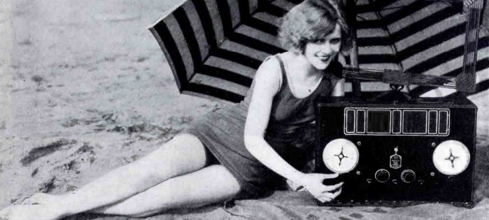
Seventy years ago, the cover of Radio Craft magazine, July 1945, featured this new radio designed for use in lifeboats. The lifeboats of passenger ships were required to be equipped with radio, and when the U.S. entered the war, this requirement was extended to cargo ships as well. The early sets were battery operated on 500 kHz and had limited range and transmitting time. The Germans were the first to develop a lifeboat radio similar to this one, the Notsender NS2. It was powered with a hand crank, and designed to be held between the operator’s legs. In addition to powering the unit, the crank keyed the transmitter, sending SOS, alternating with long dashes to facilitate direction finding. It also had provision to be keyed manually. It operated on the distress frequency of 500 kHz, and utilized a wire antenna held aloft either by a hydrogen balloon or kite.

American BC-778 "Gibson Girl."  Photo by ArnoldReinhold via Wikipedia, file licensed under the Creative Commons Attribution-Share Alike 3.0 Unported license. https://creativecommons.org/licenses/by-sa/3.0/deed.en

American BC-778 “Gibson Girl.” Photo by ArnoldReinhold via Wikipedia, file licensed under the Creative Commons Attribution-Share Alike 3.0 Unported license.

The British soon captured a few examples, and duplicated them as transmitter type T1333. In 1941, the British, recognizing that they didn’t have the industrial capacity to manufacture the sets in quantity, sought a North American builder. The U.S., recognizing the value of the unit, proceeded with the project jointly, resulting in the BC-778, later upgraded to the AN/CRT-3, which became known as the “Gibson Girl” transmitter. The earlier version, the BC-778, operated on 500 kHz exclusively. Later models also operated on 8280 or 8364 kHz. The American version could also use the generator to power a signal light.

All of the wartime units included a hydrogen generator to fill the balloon, as well as a box kite which could be used to hoist the antenna.

The accompanying article was written by an executive of the manufacturer, Radiomarine Corporation of America, and touted the advantages of the new set. It operated on both 500 kHz and on 8280 kHz, and the primary means of hoisting the antenna was with a balloon, but one filled with a helium cannister. But it had two notable differences. First of all, it was capable of transmitting radiotelephone signals as well as radiotelegraph. But it also included a receiver capable of tuning 8100 – 8600 kHz. Thus, it would allow the occupants of the lifeboat to communicate with rescuers, and also with neighboring lifeboats.

While it was not used during the war, it appears that sets similar to the one shown in the article did go into production. The model ET-8053 appears to have most of the same features, albeit in a more portable set. The model ET-8030 appears to be very similar to the one shown.

References

Click Here For Today’s Ripley’s Believe It Or Not Cartoon


1935 Two Tube Receiver

1935TwoTubePortableEighty years ago, the July 1935 issue of Popular Mechanics
showed how to make this little two-tube broadcast receiver. It uses two dual tubes, a 6F7 and 12A7. The dynamic speaker is likely unobtanium, but a similar design with a PM speaker could probably be done, although it would require a separate filter choke in the power supply. An exact duplication of the design might be a bad idea, though. Not only does the set use a “curtain burner” cord to drop the filament voltage, but one side of the power cord is hooked directly to the chassis, meaning that there’s a 50% chance that it has 120 volts on it.

According to the article, the little set pulled in stations as well as a 4 or 5 tube model, and the small size made it ideal for the traveling man, tourist, or summer home.

The chassis and case were made of heavy cardboard with a coating of shellac. The parts were mounted on a piece of aluminum which served as the actual (hot) chassis.

1935TwoTubePortableSchematic

Click Here For Today’s Ripley’s Believe It Or Not Cartoon



1937 Radio Refrigerator

RefrigeratorRadioHere’s an idea from 1937 that for some reason never caught on. As shown in the July 1937 issue of Popular Mechanics, this single kitchen appliance combines a radio and refrigerator.  Actually, as the magazine concedes, the radio is in the removable top of the refrigerator, and tops without a radio were also available.  The article doesn’t mention the manufacturer, but a handwritten note in the margin reveals that it was Crosley, who made both radios and refrigerators.  It was billed as just the thing for the housewife who wanted to listen to a recipe on the radio, or simply listen to music while working in the kitchen.

I’ve never seen any evidence of a surviving example, or even an advertisement.  So it’s unlikely that this idea got much past the trial balloon stage.

Click Here For Today’s Ripley’s Believe It Or Not Cartoon


1945 Kids Radio-Phono Combo

1945PMradiophonoThe young man shown here is presumably the son of Popular Mechanics author Arthur I. Rattray, and is shown next to the radio-phonograph assembled by his father, as described in the July 1945 issue of the magazine.

In the article, he notes that perhaps readers might have a small boy or girl who would like to play records and listen to the radio with a phono-radio combination of their very own. He notes that such units would undoubtedly be plentiful after the war, “but that does not solve the immediate problem.” Therefore, he decided to put one together himself. He did so by combining an old midget radio (probably similar to the $7.95 set featured in an earlier post) with an old table phonograph. He housed them in the legs and braces from a discarded radio console.

He ran the phono cartridge directly to the radio’s audio output tube. He noted that this hookup “does not permit full volume, which is an assset rather than a liability,” but that the volume was sufficient for both radio and phono.

I doubt if anyone is going to recreate this particular project. But one warning is in order. One side of the phono cartridge (and probably the metal tone arm) is connected directly to the radio chasis. Depending on the set, there’s a 50/50 chance that this is hooked directly to the hot side of the AC line cord.

Click Here For Today’s Ripley’s Believe It Or Not Cartoon


1950 Poolside Television

1950PoolsideTV

65 years ago, the young women shown here were enjoying the Hoffman Model 947 television poolside at the Beverly-Wilshire Hotel in Beverly Hills. The accompanying article in the July 1950 issue of Radio News notes that until recently, such activity would have been impossible, since full enjoyment of the program necessitated darkness or semi-darkness, not to mention what to do with the unwieldy line going to the antenna.

But that was all in the past, since black-faced picture tubes and improved circuit designs had resulted in greater brightness and better receiver sensitivity. A prominent motion picture star had been discussing the problem with the president of the set’s manufacturer, and had been enjoying programs poolside for quite some time. The idea soon spread, not only to the Hollywood elite, but to the area hotels.

At the Beverly-Wilshire, every warm day would find a group of swimming and sunbathing guests clustered around the set that had been wheeled out for their viewing pleasure.

And if the set ever needed servicing, the same issue advertised, for only $6.95, a high voltage probe rated at 30,000 volts, just the thing the serviceman would need if some unfortunate guest splashed a little too much water on it.

Click Here For Today’s Ripley’s Believe It Or Not Cartoon


Sackville and Dixon Transmitters, 1945

Control room of Dixon shortwave transmitters.

Control room of Dixon shortwave transmitters.

Seventy years ago, two famous RCA transmitter installations were featured in the company’s quarterly journal, Radio Age, July 1945.

The first was Canada’s shortwave transmitter at Sackville, New Brunswick, which opened on February 25, 1945. What was then referred to as “Canada’s Loudest Voice” featured two 50,000 watt RCA transmitters. The 213-acre site had been selected due to the lack of unfavorable magnetic conditions and because the moist earth was conducive to radio transmission.

Main control console at Sackville.

Main control console at Sackville.

While Canada had a number of commercial shortwave broadcasters, the intent of the station was to provide a voice comparable to that of the United States and England, in order to communicate news and entertainment to soldiers, placing the Canadian point of view before Allied nations, and to “join their fighting allies in telling the enemy the real uncolored truth about the war’s progress.”

V-E Day eliminated the need for some types of programs, but the article notes that other features would continue to expand.

Sackville transmitter site.

Sackville transmitter site.

The station, operating with the rarely stated call letters CKCX, continued in operation until 2012. In addition to CBC programs, it served as a relay for a number of other broadcasters, including Radio Japan, China Radio International, Voice of Vietnam, BBC World Service, Deutsche Welle, and Radio Korea. In addition to international programming, it broadcast CBC Northern Service programs in English, French, and Innuit.

The other RCA transmitter featured in the issue was that of the station that later became the Voice of America relay station in Dixon, California. Under contract with the Office of War Information, both CBS and NBC were contracted to construct shortwave transmitters on the West Coast to provide a strong signal to the Far East. The CBS effort resulted in what later became the VOA relay station in Delano, California. And the NBC station with its RCA transmitters featured in the RCA publication, became the VOA station in Dixon, California. That location was on a great circle that included both Asia and Latin America. Therefore, by reversing the direction of the antenna, it could cover two target areas. By beaming North, the station could provide a signal to Asia. And by beaming South, the same booming signal would carry the American message to Latin America.

The Dixon station was operated by NBC until 1963, with call letters KNBA, KNBC, KNBI, and KNBX In 1963, the federal government assumed control until the station was shut down in 1979. The installation was mothballed, and resumed operation in 1983, at which time its primary function was to transmit Spanish programming to Central America until 1988. The site was sold by the federal government in 1993, and has been used by Globe Wireless since then as KFS, providing wireless HF e-mail service to maritime interests.

Click Here For Today’s Ripley’s Believe It Or Not Cartoon


Victory Eclipse of 1945

1945EclipseSeventy years ago today, July 9, 1945, a narrow strip of Idaho and Montana experienced a total eclipse of the sun.  From its sunrise beginning in the northwestern United States, the path of totality passed through Canada, Greenland, Scandinavia, and the Soviet Union. The photo here was taken near Butte, Montana, were the sun rose almost fully eclipsed, with totality a few minutes later. The photo was taken by Peter A. Leavens, and appeared in Life Magazine on July 23, 1945.

Critical frequency during eclipse.

Critical frequency during eclipse.

Ionospheric scientists at Tromsø, Norway, only two moths after liberation, took the opportunity to measure the effects of the eclipse on the ionosphere. Their results show a pronounced dip in the critical frequency during the eclipse.

Interestingly, their report also notes that the Germans had an ionospheric station at Kjeller, used to determine radio communication frequencies after the war. When the station was taken over by Allied forces, the German peronnel were ordered to continue their work, and observations were made at that station as well.

Click Here For Today’s Ripley’s Believe It Or Not Cartoon


1951 Boys’ Life One Tube Receiver

1951BLrcvrThe one-tube shortwave receiver shown here appeared in Boys’ Life magazine in October, 1951. It’s a very simple regenerative circuit using a single 3A4 tube. According to the accompanying article (which carried no byline), the circuit was designed by the ARRL. The filaments were powered by the two dry cells in series, with a 22.5 volt battery supplying the B+. The Boys’ Life editors priced the components at $17.05 in New York, and noted that most Scouts could beat that price both by shopping around and by asking a friendly local ham for components from the junk box.
1951BLrcvrSchematicThe article is a bit sketchy on details; in fact, it doesn’t mention the tuning range. But from the size of the coil and capacitor, I’m guessing that its coverage is in the vicinity of 40 meters. The Novice class license had just been created by the FCC, and the article notes that the little receiver would be good for code practice for earning that license:

For your money and time you will have a working receiver capable of picking up amateur signals, ships at sea, aircraft, and the code-practice broadcasts of the American Radio Relay League. The League broadcasts at 9:30 P.M., Monday through Friday, at Eastern Standard Time. If you’re after the Novice Class ticket, you’ll find the ARRL broadcasts tops for real practice.

The same receiver appeared in the Radio Merit Badge pamphlet, a copy of which has been scanned and placed online by AL7FS.  It appears that the receiver appeared in the merit badge book until 1962. From the text, it appears that a requirement at that time was to construct a receiver and use it to log five stations, and this one would certainly be up to the task.

Click Here For Today’s Ripley’s Believe It Or Not Cartoon


1925 Beginner’s Crystal Set

1945RBCxtalset

1945RBCxtalsetSchematicNinety years ago, the editors of Radio Broadcast magazine, July 1925,
published detailed instructions for constructing the simple crystal set shown here. The article noted that “beginners are apt to be discouraged by the complexities which are life and nourishment to the average fan,” and vowed to also include features devoted to the beginner. It noted that “particular attention would be paid to the possibilities of five-and-ten-cent store parts,” since “the advent of the five-and-ten-cent store into the radio field has cut the cost of almost all parts.” This set could be constructed with such parts for $1.82. Antenna wire, insulators, and the headphones would bring the total to $5.52. The set was to be constructed in a cigar box which “can be stained if desired, but when merely cleaned and sand-papered, it presents a not unpleasing appearance.”

Interior view of the set.

Interior view of the set.

With the beginner in mind, the article goes into excruciating detail as to the instructions. The coil is wound honeycomb style, on a form traced onto cardboard from a template in the magazine.

For those considering replicating a similar set, I have ideas on procuring parts on my crystal set parts page.


1953 Transistor Firsts

Februay 1953 QST showing K2AH and the first transistorized amateur transmitter.  The transmitter itself is atop the tripod.

Februay 1953 QST showing K2AH and the first transistorized amateur transmitter. The transmitter itself is atop the tripod.

As far as I’ve been able to determine, the first mention of a transistor appeared in QST in June 1952 as a stray. The item reported as follows:

Amateurs whose forte is light, compact portable equipment will be interested in trasistor-technique progress reported by the Army Signal Corps. A “transistorized” radioteletype converter unit has been built which uses one-hundredth the current drain and weighs one-tenth as much as comparable vacuum-tube equipment now in service. Estimated life of the type of transistor used in the new converter is seven years for 24-hour-per-day use.

It wasn’t long until the first transistorized amateur radio transmitter showed up. It was reported in QST, January 1953. That issue’s World Above 50 Mc column noted that the transistor was “destined to have far-reaching effects on the science of electronics, but so far it had created no great stir in amateur circles.”

K2AH and his transmitter.  Popular Mechanics, May 1953.

K2AH and his transmitter. Popular Mechanics, May 1953.

The change came when George Rose, K2AH, of Mountain Lakes, N.J., worked W2KNI, W2DPB, and W2UK with “what was unquestionably the first amateur transistor transmitter, and probably the world’s record for low transmitter power.” The transmitter was pictured on the cover of the February 1953 issue and described in detail in an article by Rose in the March issue, entitled “The Transistor–Or 25 Miles on a Hunk of Germanium“.  Rose begins the article:

Most hams who can qualify for the Old Timers Club remember with mixed feelings the time spent per evening searching for that elusive spot on their pet piece of galena which would bring in NAA at a readable level, if not exactly loud and clear. Neither they nor anyone else knew why or how the thing worked in the first place. When tubes finally became commercially and financially available it was the general hope that galena and its sister crystals silicon, carborundum, etc., would be properly disposed of. They did practically vainish from the electronic scene until World War II when silicon diodes were found to outperform tubes as microwave mixers.

And since Rose was the manager of advanced development at the RCA Tube Department, he was in a position to bring home a prototype transistor to put on the air. He chose 146 MHz for the first transistorized transmitter. Even though transistors for lower frequencies were less challenging, the use of 2 meters allowed him to use his 12 element beam to get the 30-50 microwatt signal to travel a reasonable distance.

The transistor used was a PNP point-contact transistor with two phosphor-bronze cat whiskers touching a piece of germanium, separated by less than a thousandth of an inch.  The original transmitter is apparently still in existence and can be seen at this link at a 2010 Antique Wireless Association meeting.

A Stray in the April 1953 issue reports on the first QSO with a transistorized transmitter on both ends. In this case, W2JEP and W2TYH made a QSO of a half mile on 40 meters, each running about 60 milliwatts and the signal reports were S8 or S9, and the authors noted that the signals probably would have been readable at a much greater distance.

The first fully transistorized station (both transmitter and receiver) was reported in the June 1953 issue.  This station consisted of a two-transistor 10 meter AM transmitter and a two-transistor superregenerative receiver. The station made contacts with mobile stations at a club meeting within a radius of a half mile. The Stray notes that the receiver was that of W2ZKE, with other participants being K2AQM, W2GFE, W2GNE, W2NOH, W2YCX, W2YTH, and W2ZKE.

(Note:  To view the QST articles linked above, you must be logged in to your ARRL account.)

Click Here For Today’s Ripley’s Believe It Or Not Cartoon