Category Archives: Radio history

Victory Eclipse of 1945

1945EclipseSeventy years ago today, July 9, 1945, a narrow strip of Idaho and Montana experienced a total eclipse of the sun.  From its sunrise beginning in the northwestern United States, the path of totality passed through Canada, Greenland, Scandinavia, and the Soviet Union. The photo here was taken near Butte, Montana, were the sun rose almost fully eclipsed, with totality a few minutes later. The photo was taken by Peter A. Leavens, and appeared in Life Magazine on July 23, 1945.

Critical frequency during eclipse.

Critical frequency during eclipse.

Ionospheric scientists at Tromsø, Norway, only two moths after liberation, took the opportunity to measure the effects of the eclipse on the ionosphere. Their results show a pronounced dip in the critical frequency during the eclipse.

Interestingly, their report also notes that the Germans had an ionospheric station at Kjeller, used to determine radio communication frequencies after the war. When the station was taken over by Allied forces, the German peronnel were ordered to continue their work, and observations were made at that station as well.

Click Here For Today’s Ripley’s Believe It Or Not Cartoon


1951 Boys’ Life One Tube Receiver

1951BLrcvrThe one-tube shortwave receiver shown here appeared in Boys’ Life magazine in October, 1951. It’s a very simple regenerative circuit using a single 3A4 tube. According to the accompanying article (which carried no byline), the circuit was designed by the ARRL. The filaments were powered by the two dry cells in series, with a 22.5 volt battery supplying the B+. The Boys’ Life editors priced the components at $17.05 in New York, and noted that most Scouts could beat that price both by shopping around and by asking a friendly local ham for components from the junk box.
1951BLrcvrSchematicThe article is a bit sketchy on details; in fact, it doesn’t mention the tuning range. But from the size of the coil and capacitor, I’m guessing that its coverage is in the vicinity of 40 meters. The Novice class license had just been created by the FCC, and the article notes that the little receiver would be good for code practice for earning that license:

For your money and time you will have a working receiver capable of picking up amateur signals, ships at sea, aircraft, and the code-practice broadcasts of the American Radio Relay League. The League broadcasts at 9:30 P.M., Monday through Friday, at Eastern Standard Time. If you’re after the Novice Class ticket, you’ll find the ARRL broadcasts tops for real practice.

The same receiver appeared in the Radio Merit Badge pamphlet, a copy of which has been scanned and placed online by AL7FS.  It appears that the receiver appeared in the merit badge book until 1962. From the text, it appears that a requirement at that time was to construct a receiver and use it to log five stations, and this one would certainly be up to the task.

Click Here For Today’s Ripley’s Believe It Or Not Cartoon


1925 Beginner’s Crystal Set

1945RBCxtalset

1945RBCxtalsetSchematicNinety years ago, the editors of Radio Broadcast magazine, July 1925,
published detailed instructions for constructing the simple crystal set shown here. The article noted that “beginners are apt to be discouraged by the complexities which are life and nourishment to the average fan,” and vowed to also include features devoted to the beginner. It noted that “particular attention would be paid to the possibilities of five-and-ten-cent store parts,” since “the advent of the five-and-ten-cent store into the radio field has cut the cost of almost all parts.” This set could be constructed with such parts for $1.82. Antenna wire, insulators, and the headphones would bring the total to $5.52. The set was to be constructed in a cigar box which “can be stained if desired, but when merely cleaned and sand-papered, it presents a not unpleasing appearance.”

Interior view of the set.

Interior view of the set.

With the beginner in mind, the article goes into excruciating detail as to the instructions. The coil is wound honeycomb style, on a form traced onto cardboard from a template in the magazine.

For those considering replicating a similar set, I have ideas on procuring parts on my crystal set parts page.


1953 Transistor Firsts

Februay 1953 QST showing K2AH and the first transistorized amateur transmitter.  The transmitter itself is atop the tripod.

Februay 1953 QST showing K2AH and the first transistorized amateur transmitter. The transmitter itself is atop the tripod.

As far as I’ve been able to determine, the first mention of a transistor appeared in QST in June 1952 as a stray. The item reported as follows:

Amateurs whose forte is light, compact portable equipment will be interested in trasistor-technique progress reported by the Army Signal Corps. A “transistorized” radioteletype converter unit has been built which uses one-hundredth the current drain and weighs one-tenth as much as comparable vacuum-tube equipment now in service. Estimated life of the type of transistor used in the new converter is seven years for 24-hour-per-day use.

It wasn’t long until the first transistorized amateur radio transmitter showed up. It was reported in QST, January 1953. That issue’s World Above 50 Mc column noted that the transistor was “destined to have far-reaching effects on the science of electronics, but so far it had created no great stir in amateur circles.”

K2AH and his transmitter.  Popular Mechanics, May 1953.

K2AH and his transmitter. Popular Mechanics, May 1953.

The change came when George Rose, K2AH, of Mountain Lakes, N.J., worked W2KNI, W2DPB, and W2UK with “what was unquestionably the first amateur transistor transmitter, and probably the world’s record for low transmitter power.” The transmitter was pictured on the cover of the February 1953 issue and described in detail in an article by Rose in the March issue, entitled “The Transistor–Or 25 Miles on a Hunk of Germanium“.  Rose begins the article:

Most hams who can qualify for the Old Timers Club remember with mixed feelings the time spent per evening searching for that elusive spot on their pet piece of galena which would bring in NAA at a readable level, if not exactly loud and clear. Neither they nor anyone else knew why or how the thing worked in the first place. When tubes finally became commercially and financially available it was the general hope that galena and its sister crystals silicon, carborundum, etc., would be properly disposed of. They did practically vainish from the electronic scene until World War II when silicon diodes were found to outperform tubes as microwave mixers.

And since Rose was the manager of advanced development at the RCA Tube Department, he was in a position to bring home a prototype transistor to put on the air. He chose 146 MHz for the first transistorized transmitter. Even though transistors for lower frequencies were less challenging, the use of 2 meters allowed him to use his 12 element beam to get the 30-50 microwatt signal to travel a reasonable distance.

The transistor used was a PNP point-contact transistor with two phosphor-bronze cat whiskers touching a piece of germanium, separated by less than a thousandth of an inch.  The original transmitter is apparently still in existence and can be seen at this link at a 2010 Antique Wireless Association meeting.

A Stray in the April 1953 issue reports on the first QSO with a transistorized transmitter on both ends. In this case, W2JEP and W2TYH made a QSO of a half mile on 40 meters, each running about 60 milliwatts and the signal reports were S8 or S9, and the authors noted that the signals probably would have been readable at a much greater distance.

The first fully transistorized station (both transmitter and receiver) was reported in the June 1953 issue.  This station consisted of a two-transistor 10 meter AM transmitter and a two-transistor superregenerative receiver. The station made contacts with mobile stations at a club meeting within a radius of a half mile. The Stray notes that the receiver was that of W2ZKE, with other participants being K2AQM, W2GFE, W2GNE, W2NOH, W2YCX, W2YTH, and W2ZKE.

(Note:  To view the QST articles linked above, you must be logged in to your ARRL account.)

Click Here For Today’s Ripley’s Believe It Or Not Cartoon


Steam Powered CW Transmitter

SteamPoweredHamTX

QRP’ers wanting to get on the air with a novel power source will appreciate the steam powered transmitter that appeared in Popular Electronics fifty years ago this month, July 1965.

The author, Hartland B. Smith, W8VVD, describes a one-transistor crystal controlled transmitter with a power output of 10-15 milliwatts, powered by a DC motor attached to a model steam engine. The motor (being used as a generator) was on a hinged mount, with a rubber grommet contacting the steam engine flywheel and with a rubber band providing the necessary tension. The rig was tested with 3 volts, but the generator was said to put out up to six volts.

The steam engine manufacturer recommended (as they still do) the use of dry fuel tablets, but the author noted that anything from a candle to a propane tank could be used. To avoid the need for frequent refueling, the author settled on a propane tank, resting between two wooden blocks.

The author notes that almost any of the model engines on the market would be up to the task, but he recommended one with a fairly large boiler to avoid delays caused by needing to refill and build up a new head of steam.

Model steam engines, practically identical to the one shown in the 1965 article, are still available, although they can be a bit pricey. My son owns a Jensen Model 75, although I don’t think we paid anywhere near its current price on Amazon. The Wilesco Model D5 appears comaprable, at a more reasonable price. Either should put out more than adequate power to run a small transmitter similar to the one shown in the article. The tank does appear somewhat smaller than the one in the article, but will give several minutes of run time, enough for a short QSO, if not a long ragchew. We power ours with the Esbit Dry Fuel Tablets, although it could easily be run with alcohol. Because of the smaller tank, it would probably be tricky to rig it up to run from the propane tank, although that could probably be managed.

The author Hartland Smith was first licensed in 1941, and is still licensed as W8QX.  In addition to writing, he worked as a broadcast engineer, designer, and kit manufacturer.  He has a number of interesting websites which he has linked at this one.  I received a nice e-mail from him, in which he mentioned that had written a number of other articles for “PopTronics.”  I did a search and located quite a few, including the “Camper’s Special” from 1965 and the “Camper’s Cuzzin” from 1967.  Together, they formed an 80 meter QRP station suitable for camping or emergency backup.  The “Camper’s Special” was a crystal-controlled transmitter that put out 5 watts.  The author points out (as many of us later discovered with the modern rediscovery of QRP) that this is just two S-units weaker than a 100 watt signal.  The “Camper’s Cuzzin” was a companion receive converter, which allowed the builder to tune the 80 meter band on a standard broadcast receiver.  It contained three transistors, a local oscillator tuning 5.1 – 5.6 MHz, an amplifier-mixer, and a BFO set to 1.6 MHz.  By setting the converter next to a portable AM radio tuned to 1600, the result was that 80 meter CW or SSB could be heard.

He also designed two transmitters for the novice.  The “Hart-25” from 1955 put out 25 watts, and the “Hart-65” in 1967 put out 65 watts on 80 and 40.

For those looking for an even more challenging QRP transmitter, check out AA1TJ’s voice powered “CW” transmitter described at this link and seen in action on this video.  He worked a QSO of a hundred miles with no power source other than his own voice into a PM speaker.  It was probably quite a bit more than two S-units below a 100 watt signal, but by shouting loud enough, he made QSO’s without any power source, steam or otherwise.

Click Here For Today’s Ripley’s Believe It Or Not Cartoon


1945 Taxi Radio

1940TaxiRadio2Seventy years ago, the concept of installing two-way radio in a taxi was a new one, as shown in this article from the July 1945 issue of Popular Mechanics.

An experimental system was being tried out in Cleveland, using FM on 118 MHz.  The article correctly predicted that the experiment had proved so successful that it would be a postwar economic necessity for many cab companies.

Both the fixed and mobile stations used fifteen watts, and the experiment showed that this power level provided static free reception throughout the Cleveland area.

The Motorola mobile unit, shown below, was mounted in the trunk of the vehicle. The equipment originally covered what we today call the “low band” (30-50 MHz) and had to be converted on the experimental frequency of 118.65 MHz. Clearly visible in the photo is the dynamotor, which was a motor-generator set. The motor ran on the DC voltage from the car battery (probably 6 volts) and drove a high-voltage DC generator to power the equipment. A control head, along with a telephone handset, was mounted in the vehicle for the driver to operate the radio.

1940TaxiRadio1

Click Here For Today’s Ripley’s Believe It Or Not Cartoon


1940 “Mighty Midget” One Tube Shortwave Receiver

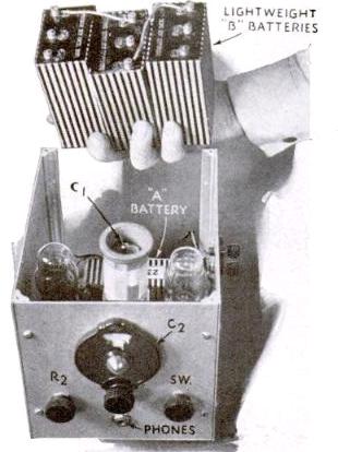
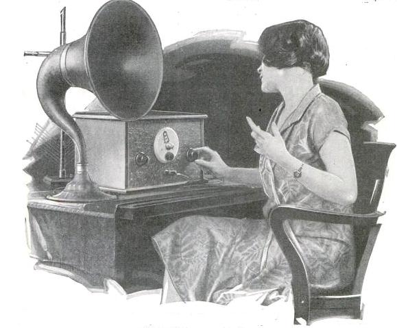
1940JulyPMrxSeventy five years ago, the father and daughter shown here were putting together a one-tube shortwave receiver according to plans in the July 1940 issue of Popular Mechanics.

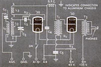
The set, the “Mighty Midget” One Tuber, employed a single 1D8-GT, a dual tube, with one half being used as the regenerative detector and the other half serving as an audio amplifier.

Thanks to the efficiency of the multi-unit tube, the set was said to run rings around two-tube receivers of even a year earlier.  “Twenty-meter phone stations roll in with headphone volume at times actually uncomfortable, and there is plenty of ‘sock’ even on weak foreign stations.”

For information on sourcing parts, especially the plug-in coils, see my recent post about a similar two-tube set.

1940JulyPMpic


1940JulyPMschematic

Click Here For Today’s Ripley’s Believe It Or Not Cartoon


More CONELRAD Crystal Sets

1956 Boys' Life Conelrad Receiver.

1956 Boys’ Life Conelrad Receiver.

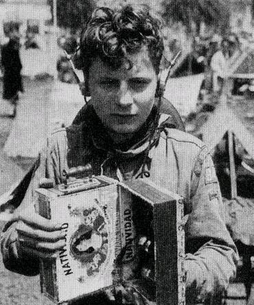
We’ve had a number of posts about the use of crystal sets for reception of CONELRAD signals.   For example, a 1956 Boys’ Life article contained instructions for building a one-transistor set for use in receiving CONELRAD during an attack.  A later 1965 article pared down the set to a simple crystal set.

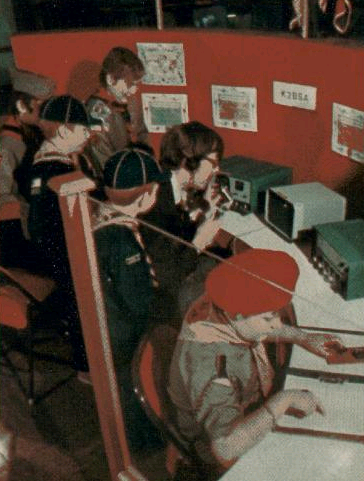
Boy Scout and Civil Defense leaders in Spokane apparently thought it was a good idea, as reported in the November 24, 1958 issue of the Spokane Daily Chronicle.

Chester L. Brown, the civil defense communications chief, prepared a special bulletin on Conelrad crystal radio receivers, which were distributed by Boy Scouts of the Inland Empire Council.

According to the article, the idea was suggested by a scout mother who had been active in civil defense. She had read a newspaper article in which an Atomic Energy Commission official had proposed that all households should be equipped with a receiver capable of operating without commercial power.

The CD pamphlet contained a diagram for a set, and noted that the parts could be purchased in kit form for as little as $1.25.


Click Here For Today’s Ripley’s Believe It Or Not Cartoon


1924 Portable

1924AprilRadioAgePortable

Miss Claire Patton is shown here in the April 1924 issue of Radio Age
showing off one of the latest portables. This exceptionally compact set featured six tubes and a loop aerial contained within the small case. The set could pick up stations 800 miles away with headphones.

Click Here For Today’s Ripley’s Believe It Or Not Cartoon



1915 Military Mobile Wireless

1915MCA hundred years ago, the setup shown here was the state of the art in mobile military communication. The illustration, which appeared in the June 1915 issue of Popular Mechanics, is a combination radiotelegraph and radiotelephone station which was carried in a motorcycle sidecar. It was powered by a DC dynamo run by a separate motorcycle engine mounted in the sidecar. It contained two transmitters, one for radiotelegraph, and one for radiotelephone. The transmitting range was stated as being approximately 100 miles for telegraphy and half that distance for telephony.

The outfit included a telescoping steel mast, which was transported strapped securely to the side of the machine.

Click Here For Today’s Ripley’s Believe It Or Not Cartoon