Category Archives: Radio history

1955 Motorola Clock Radio

1955MotorolaClockRadio

Sixty years ago, this week’s issue of Life Magazine carried this ad for Motorola’s latest clock radio.  For $39.95, this handsome set told the time and date, and would sing you asleep at night and sing you awake in the morning.  As an added bonus, it would have your coffee waiting.

The last item was accomplished by having a switched AC outlet on the back of the radio, which came on when the radio did.  All you would need to do would be to plug your electric percolator into the radio.  Since the radio was presumably in the bedroom, you would need to make the coffee there as well, unless you had a heavy-duty extension cord.

Click Here For Today’s Ripley’s Believe It Or Not Cartoon


1945 Los Angeles Radio and TV

101045RadioHightlights

Here is what was on the radio 70 years ago today, October 10, 1945, in Los Angeles.  This listing is taken from that week’s issue of Radio Life, which contains, in addition to these highlights, the complete program listings.

You’ll see that there are three television programs, on station W6XYZ, the predecessor of KTLA.  The station was owned by Paramount, received its construction permit in 1939, and came on the air for the first time in 1942, on channel 4.   The station received its commercial license and the KTLA call letters in 1947, the first commercial television station west of the Mississippi.

On this day, starting at 8:00 PM, the station signed on with a test pattern that ran for a half hour, followed by “Scanning the Globe” at 8:30, “Fashion Guide” at 8:45, and “Variety” at 9:00.

Click Here For Today’s Ripley’s Believe It Or Not Cartoon



Science Fair Ideas: Homemade Batteries from 1965

HomemadeBattery3

When the aspiring young mad scientist is looking for ideas for the science fair, someone invariably suggests making a homemade battery. Making a battery is a fairly simple proposition. All you need are two dissimilar metals and an electrolyte. A common choice for electrolyte is a mild acid such as lemon juice, and copper and zinc make good dissimilar metals. No matter how badly you construct the thing, a little bit of electrical current is bound to flow, and you can probably coax a little bit of light out of a light-emitting diode (LED) or even power a small electronic device such as a digital clock.

A good choice for the kids who aren’t as smart as you are.

In fact, for students with limited scientific abilities, you can just go out and buy yourself a Potato Clock kit. You simply open the box and jab the electrodes into a potato, and the potato juice serves as the electrolyte. It’s completely safe, since I can hardly think of any chemical more benign than potato juice. If you drop the potato on the floor, you don’t need to bother calling the haz mat team. And unless you screw up horribly, the clock will instantly come to life. There’s nothing wrong with the humble potato clock, but if you’re reading this looking for ideas, you probably want to come up with something a bit more spectacular. And while you’re at it, you probably want to use chemicals slightly more dangerous than potato juice.

So you might want to go back in history a bit when adults weren’t quite so concerned with hazardous chemicals, and use something slightly more powerful in making your battery. You can go back in time fifty years, when adults let their responsible children play around with slightly more dangerous chemicals such as household bleach, often referred to by its most popular brand name, Clorox. Not only will you have more fun, but you’ll wind up with a much more powerful battery, suitable for powering much bigger electronic devices.

For details on how to put the battery together, you can go to page 98 the Fall 1965 issue of Elementary Electronics.  That article describes two batteries that you can make at home, both of which are hundreds of times more powerful than the one running that other kid’s potato clock.

Warning:  Bleach really is a dangerous chemical.  You need to be careful with it, and keep it out of the reach of children who are not as smart as you are.  If you get any on your clothes, your mom will be mad.  If you get any in your eyes, you’re facing a major medical emergency.  Your mom is probably right when she tells you, “you can put an eye out with that.”  Ask your parents and/or teacher for permission.  If they balk at the idea, ask them to read the article about how to make the battery.  To show how responsible you are, show them that you read the Material Safety Data Sheet (MSDS).

Homemade battery using drops of bleach.

Battery using drops of bleach.

The article shows how to make two batteries.  The first one, while much more powerful than the potato, is “more of a novelty than a practical device.”  It is shown here, and consists of fifteen sets of aluminum strips and copper wires. The metallic pieces are arranged in a circle around a piece of Plexiglas. The copper and aluminum are close together, but not touching.  When ready for use, a drop of bleach is placed on each one.  When the last drop of bleach is added, the connected radio or other device springs to life.  If measured with a voltmeter, the complete battery will put out about 15 volts.  However, this drops when there’s an actual load, and 15 cells is about right to power a radio that normally calls for 9 volts.

Unlike the potato battery, this one will run a radio for several minutes.  But the article concedes that it’s more of a novelty.  Therefore, the article goes on to describe another more powerful battery.  The bigger one is even suitable for use around the house in case of a power outage.  If the power is out and you’ve used up the last battery, there’s probably still a bottle of bleach down in the laundry room, good for hundreds of homemade batteries.

HomemadeBattery2

Homemade battery using ice cube tray.

The larger battery is constructed in a plastic ice cube tray.  You use six of the individual compartments, so you can cut the ice cube tray in half and make two batteries.  Each compartment of the tray contains one piece of aluminum and one piece of copper.  You simply fill each compartment with bleach, and you have enough power to run a radio for several hours.  When the battery finally goes dead, you pour out the old bleach and replace it.  You can re-use the battery hundreds of times before the aluminum finally gets worn away completely.

Voltaic pile similar to the 1799 version. Wikipedia photo.

With either battery, you have essentially recreated the work of Allesandro Volta, who invented the Voltaic pile in 1799.  He was eventually able to build a battery large enough to administer an uncomfortable electric shock.  Until the electric generator came along in the 1870’s, anything that required electricity (such as the telegraph or telephone) was powered by batteries similar to those created by Volta.

Armed with this fifty year old article, a bottle of bleach, and a few pieces of scrap metal, you can now make your own Voltaic pile.  You’ll get to use dangerous chemicals.  You can generate significant amounts of electrical power.  Perhaps you can even administer uncomfortable electric shocks to your friends, teachers, and parents.

You’ll have the most interesting project at the science fair.  And the kid who goes home with a participation ribbon for his potato clock is going to be pissed.

Check out my other science fair ideas, some of which are slightly dangerous.

Click Here For Today’s Ripley’s Believe It Or Not Cartoon


1940 3-tube Loudspeaker Set

1940PS3tube2

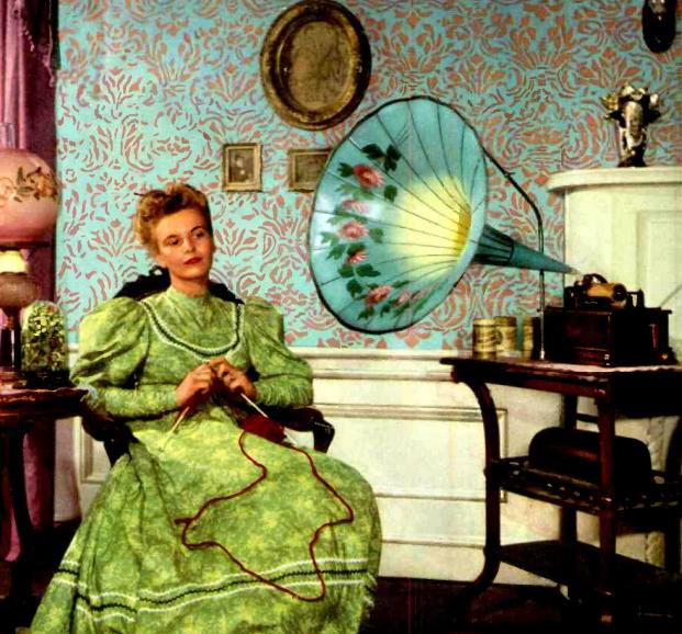
This little three-tube broadcast set could be put together for $4.04, according to the project description in the October 1940 issue of Popular Science.  The article described the AC-DC broadcast set as “simplicity itself,” with three tubes, a 43, a 6C6, and a 25Z5. With a short antenna, it had enought “pep” to drive the 93 cent speaker, and the chasis consisted of an aluminum cake pan. The cabinet was made of pieces of scrap wood.

1940PS3tubeOne interesting feature was the use of honeycomb style coils for the regenerative detector. They were wound on two cardboard disks, the tickler coil 3-1/4″ diameter, with the antenna coil 2-3/4″ diameter. The two coils were mounted above the chassis on brass screws and spacers, 3/4″ apart.

While the set was designed to cover the broadcast band, the author noted that the range could be adjusted up or down a bit by adding or removing turns from the antenna coil.

Click Here For Today’s Ripley’s Believe It Or Not Cartoon


Radio Scouting in 1940

Radio and scouting have a long association, as shown by these two photos from 75 years ago this month, in the October 1940 issue of Boys’ Life1940OctBLThe first shows scout Edwin Parkerson of Troop 50, Houston, Texas, listening to music in this set he built to bring to camp.  A scout is kind, and Parkerson undoubtedly let his friends take a turn listening shortly after this picture was taken.

Assuming he did share the headphones, it was probably good for a bit of karma.  Sixteen years later, one Edwin Parkerson of Houston renewed his hospitalization insurance policy, but due, no doubt, to some little mix-up, the premium check bounced.  The insurance company apparently put the check through a second time without incident.  But during the intervening time, Mr. Parkerson’s wife was taken to the hospital, and the insurance company claimed that the policy wasn’t in effect and denied coverage.  The Texas Court of Civil Appeals ruled that the policy was in effect.  Parkerson v. American Hospital Life Ins. Co., 322 S.W.2d 26 (Tex. Civ. App. 1959).

While scout Parkerson was listening to the radio through headphones, the scouts in Nashville were probably getting ready to build a loudspeaker set, since they’re shown here getting some pointers from the staff of WSM.  The caption reports that nearly a hundred Nashville scouts had formed a radio patrol, and were getting technical lessons from the station’s technical staff.

1940OctBL2

Click Here For Today’s Ripley’s Believe It Or Not Cartoon


SD’s Betsy Ross and KGFX, Pierre

KGFX194074 years ago, Life Magazine, October 6, 1941, carried this image of Ida McNeil, the owner and operator of KGFX, Pierre, South Dakota.

If the studio looks a bit cramped, that’s because it is located in her home at 510 Summit Avenue, Pierre, SD.  Both the transmitter and studio remained at that location until 1958, when the transmitter was moved to Ft. Pierre.  The studio remained at the McNeil home until 1964.

The station’s roots date back to 1912 when Ida’s husband, Dana McNeil, was first licensed as 9ZP.  In 1916, he was licensed as 9CLS.  According to the FCC’s card file for the station, the broadcast license for KGFX was first issued on August 15, 1927, with the licensee listed as Dana McNeil,  The station was originally at 1180 kHz, moving to 580 kHz in 1928. In 1932, it moved to 630 kHz, where it remained until 1967.

The 1932 move from 580 appears to be prompted by WNAX, 180 miles away in Yankton, which applied on March 9, 1932, to increase its power on 570 kHz. The WNAX application is referenced in KGFX’s FCC record. WNAX has one of the largest coverage areas of any AM station in the country, and moving KGFX away from the adjacent channel was probably necessary to make that possible.

In 1967, the station made its final move on the dial to its present day 1060 kHz, with 10 kilowatts daytime and a pre-sunrise authority of 500 watts. In 1974, the station was granted authority to run 1000 watts at night.

Mr. McNeil died in 1936, and the FCC record shows the license transferred to Ida McNeil, as the administratrix of his estate, effective March 26, 1937. The license remained in her name until 1962, when it was transferred to Black Hills Radio, Inc.  In 1940, when this photo was taken, the FCC record shows that the station was licensed with 200 watts on 630 kHz between 9:30 AM and local sunset.

Even though the station was licensed commercially, the McNeils operated it as a public service, believing that radio stations should serve the community. The station began accepting commercial advertising in 1932, but the majority of the air time was still devoted to public service. One of the station’s most popular programs was “Hospital News,” in which she broadcast announcements regarding the condition of patients at Pierre’s St. Mary’s Hospital. The physicians at the hospital were initially dismayed by the idea of public announcements about their patients, which they viewed as unethical. But because of difficulties with transportation and communication in rural South Dakota, they soon realized that the program provided a valuable public service, and gave their cooperation.

South Dakota flag, 1909-1963.

South Dakota flag, 1909-1963.

Being a broadcaster was not Mrs. McNeil’s only claim to fame.  Life magazine identified her as the Betsy Ross of South Dakota, since she had designed the state’s flag in 1909, her design remaining in use until 1963.

Mrs. McNeil was born Ida Anding in 1888 in Winona, Minnesota. Her father was a steamboat engineer, and the family moved to Pierre in 1896 when he came to supervise the overhaul of a ferry. She graduated from high school in 1906 and went to work for the South Dakota Department of History, where she was employed when she designed the state flag.

She married Dana McNeil, a railroad conductor, in 1921. While he was on runs between Rapid City and Pierre, she began broadcasting to him over his amateur station. After she realized that he was not the only listener, she began developing a regular programming format, and they obtained the commercial license for KGFX in 1927. In addition to running the radio station, she served as the weather bureau’s official observer between 1935 and 1942.  She died in 1974 at the age of 86, having retired from the radio business with the sale of the radio station twelve years earlier.

Click Here For Today’s Ripley’s Believe It Or Not Cartoon


Hytron Tube Test Station, 1944

Hytron1945The wartime Hytron Corporation worker shown here is using a tube tester, but it’s probably a bit bigger than the one down at the drug store. She is operating a master test station for measuring various attributes of transmitting vacuum tubes. It was described in the October 1944 issue of Radio News.

A year later, the editors were undoubtedly looking for a stunning picture for the cover, so they went ahead and used it 75 years ago this month, in the October 1945 issue.

The test station had various power supplies, as well as precise measuring instruments for voltages and currents to each tube element. The nicely crafted drawers provided storage space for jumper cables and adapters. The heights and angles of all of the meters were carefully considered to avoid paralax errors.

Hytron was acquired by CBS in the 1950’s, and was a major producer of tubes under the Hytron CBS label.

Click Here For Today’s Ripley’s Believe It Or Not Cartoon



Profile in Courage: Jack van der Zee, 1980

MS Prinsendam. Wikipedia photo.

MS Prinsendam. Wikipedia photo.

Thirty five years ago today, Chief Radio Officer Jack van der Zee performed an act of heroism that was later recognized by Queen Beatrix. On October 4, 1980, the passenger ship MS Prinsendam of the Holland-America line was in severe distress off the coast of Alaska with about 350 passengers and 200 crew.  There was a fire in the engine room, the ship was being flooded, and it ultimately sank.

Due to the lateness of the hour, few vessels in the area were monitoring the radio, although virtually every vessel at sea was equipped with an automatic alarm to alert for any SOS calls.  The Prinsendam contacted the U.S. Coast Guard, which advised that the ship should send an SOS to alert the vessels in the area to assist in the rescue.  The decision rested with the ship’s master,  Cornelis Dirk Wabeke. Captain Wabeke refused to do so.  Because the SOS would allow assisting ships to assert salvage rights, he instead ordered radio officer van der Zee to send the message as a mere “urgent” message.  Since the radio officers of nearby ships would not be at their stations, van der Zee realized that no nearby ship would hear the message.

Van der Zee, already feeling the heat of the fire through his shoes, made a courageous decision.  Realizing full well that the decision could result in loss of his job and pension, and even imprisonment for mutiny, decided to ignore the captain’s order.  Instead, he sent the message as an SOS, prefaced by the signals that would activate the automatic alarms of other nearby ships.

Within minutes, other ships were alerted to the looming disaster, and raced to the scene to assist.  Within hours, the ship was sunk, but U.S. and Canadian military and Coast Guard rescuers were on the scene, assisted by the civilian vessels alerted by van der Zee’s mutinous act,

For his act of heroism, van der Zee was recognized by  Queen Beatrix by the award of the Order of the Netherlands Lion.

An audio file of van der Zee’s call  of SOS DE PJTA, along with more details and documents, can be found at this link at archive.org.  Also see the web page of N1EA, one of the other operators (of the supertanker WIlliamsburgh, WGOA) who assisted in the rescue.

Click Here For Today’s Ripley’s Believe It Or Not Cartoon


1945 Car Radio Conversion

1945CarRadioConversion

Seventy years ago, the war was over, but radios were not yet available to consumers, since production had been shut down on April 22, 1942.  Gasoline rationing had already ended, but after years of tight restrictions on both tires and gasoline, it was likely that there were a lot of car radios that weren’t seeing much use.  Therefore, it’s quite likely that many owners of car radios took the lead of the gentleman shown here, and converted the car set for use inside.  The October 1945 issue of Popular Mechanics showed how to make the relatively simple conversion.

The conversion required only a few parts.  First of all, the car’s 6-volt battery was replaced with a 4-amp filament transformer.  Since the transformer put out AC, the vibrator in the car radio was no longer necessary.  Therefore, it was simply removed and jumpered.  The car radio would have a speaker with a 6-volt dynamic coil, which wouldn’t work well with AC.  Therefore, it was simply replaced with a permanent magnet speaker.  The rectifier tube, a 0Z4, was replaced with a 6X5.  Since the set’s existing power supply filter might not be up to the job of getting rid of all of the 60 cycle hum, the article showed where a choke could be added if hum was still a problem.

The set could be housed in a new cabinet or, as shown here, in a desk drawer.

Click Here For Today’s Ripley’s Believe It Or Not Cartoon


1958 Worm Catcher (Kids: Don’t Try This At Home)

1958WormCatcher

If the project shown in this photo looks dangerous to you, well, that’s probably because it is dangerous.

WARNING:  Do not construct the worm shocker shown on this page!  This is not a construction article.  It is an interesting historical look back at an earlier time when people didn’t worry quite so much about things like electrocution.  

If you ignore my advice, don’t sue me if something goes wrong (and that goes for your heirs, as well).

This illustration appears in the 1958 edition of the Electronic Experimenter’s Handbook, published by Popular Electronics.  It is exactly what it appears to be, namely, an AC line cord attached to two metallic probes.  One of the probes has rubber tape near the wooden handle.  The other one has not yet received this gesture toward safety.

Another warning:  If you insist on building this contraption, you must not plug this probe directly into an outlet.  It is plugged into a circuit which provides a small amount of safety.  If plugged directly into household current, it would be positively lethal, instead of just extremely dangerous.  (In fact, if you insist on doing this, it would be a good idea to use a plug rated at 120 volts, but one that does not fit into the normal household outlets, lest someone sees this one part and decides to plug it in to see what it does.)

With all of my earnest warnings out of the way, I’ll disclose what this is. It isn’t a torture device, at least not one for humans.  It’s actually part of a worm catcher, a labor-saving device that will bring earthworms to the surface for easy collection.  It does so by sending household current through the soil.  You stick the probes into the ground, about 3 feet apart, and then plug the probes into the accompanying power supply (and not directly into a wall outlet).  The worms will experience the discomfort of electrical current passing through them, and in an effort to escape, they’ll come to the surface where you can harvest them.

The accompanying article describes two power supplies. The first one consists of little more than two ten-watt light bulbs, one in series with each side of the AC line. The whole circuit is mounted in a wooden box. “Wood was used in this case because of its insulating properties.”

This circuit will undoubtedly trip a modern GFCI outlet. (And by code, any outside outlet should be protected by a GFCI.) Therefore, it probably wouldn’t work today.   I’m not going to explain why it wouldn’t work.  If you don’t know, then you should definitely not build either of these until you’ve brushed up on your electrical theory.

The second circuit is slightly safer, because it includes an isolation transformer. It’s still dangerous, because you’re still playing with 120 volts. It simply eliminates a few of the many possible methods of lethal electrocution. Like the other model, it drops the line voltage somewhat by passing the current through two light bulbs, in this case a 75 watt and a 25 watt in parallel. Since these bulbs probably wouldn’t glow brightly enough to see if the unit is energized, there is a test switch to temporarily remove the 75 watt bulb from the circuit. When the test button is pushed, the 25 watt bulb will provide a visual cue that the probes are correctly in place and the worms are on their way to the surface.

The article does contain a few safety warnings of its own. One of the descriptions starts with the self-evident comment that “the safety factor is the biggest problem involved in the use of house current.” It also warns: “Don’t take any chances by moving the probes when the unit is turned on.”  If the energized probes are safely underground, the effects will presumably be felt only by the worms.  And since the soil is not a perfect conductor, it’s probably not lethal to the worms.  But if the probes are out of the ground while energized, then they pose a hazard to humans in the area.

The editors also add the caution: “Do not attempt to modify either of these circuits. If wired according to the schematics, they will provide [somewhat] adequate protection from the LETHAL 117-volt a.c. household line.”

One warning that’s not mentioned in the article bears repeating.  It notes that if the ground is dry, then watering the ground first could improve performance.  This stands to reason, since damp soil is obviously more conductive than dry soil.  But it also highlights the fact that damp shoes (or bare feet) are better conductors than dry shoes.  So if you insist, despite my warnings, to attempt this method of worm collection, please make sure you’re wearing dry non-conductive shoes.

And remember:  Kids:  Don’t try this at home!


Click Here For Today’s Ripley’s Believe It Or Not Cartoon