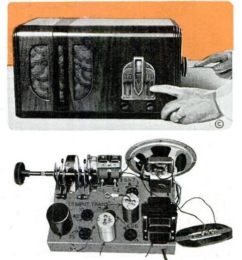
The plans for this five-tube superhet, dubbed the “High Fidelity Five,” appeared in Popular Mechanics 75 years ago this month, October 1940. It got this name due to its tone control circuit, which enabled the “small set to have a bass response comparable to that of a large receiver,” since the circuit could amplify the lower tones without distortion. The set also featured mechanical pushbutton tuning, with a tuning assembly that was commercially available. The project was not designed for beginners, but was “quite simple and well within the building range of the average experimenter.” Cabinet details were given, but the article mentioned that suitable cabinets were available for purchase.
The set had a transformer for both the B+ and filament voltages, and employed a electro-dynamic speaker, with the field coil also serving to filter the output of the power supply. While the full schematic and pictorial diagrams were given in the article, blueprints were also available for purchase.
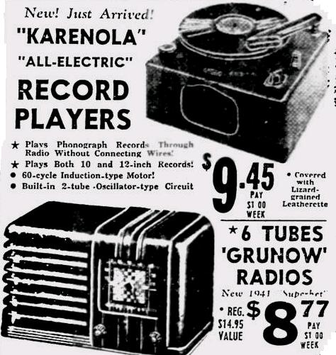
If you were looking for a low-cost radio or phonograph 75 years ago today in Milwaukee, then Economy Boys would be the store to visit. In the store’s ad in the October 24, 1940, issue of the Milwaukee Journal,
we see this six-tube Grunow superhet broadcast receiver for just $8.77.
The phonograph, selling for just $9.45, is actually a “phono oscillator.” Instead of including an audio amplifier and speaker, this Karenola model contains a two-tube oscillator circuit, which broadcasts the radio sound to a nearby broadcast radio. Even if the radio is a low-price model without a phono jack, you simply tune to a blank spot on the dial to listen to your records.
At Economy Boys, you could take home either set for just a dollar a week.
Unfortunately, I wasn’t able to pin down the model number of either. Most Grunow radios I’ve seen had wood cabinets, and this one appears to be plastic or bakelite. The Karenola name is probably more familiar as Trav-Ler, since the phonograph was from the Trav-Ler Karenola company of Chicago.
It’s generally accepted in the history of science and technology that radio couldn’t have been invented until James Clerk Maxwell came up with Maxwell’s Equations in 1865. That theoretically underpinning of radio were verified experimentally by Heinrich Hertz in 1887. (Hertz, it turned out, was using electromagnetic waves of about two meters in wavelength, it turns, meaning that the first intentionally generated radio waves were probably in or near the two meter amateur band.)
The prevailing wisdom, which is more or less true, is that someone like Guglielmo Marconi in the 1890’s couldn’t have come along and turned radio into a practical device without the prior work of Maxwell and Hertz.
While that statement is generally true, it ignores Dr. Mahlon Loomis, a dentist and inventor who was born in 1826 and died in 1886, the year before Hertz’s experiments. And it appears that in 1866, he successfully communicated wirelessly between two mountains fourteen miles apart. Unfortunately, he produced no independent witnesses to verify the claim. And his understanding was that some layer of the sky was completing a direct-current circuit, using the atmosphere as a conductor to send the direct current.
Even though his explanation is impossible, it’s likely that he was sending and receiving radio signals. FIrst of all, his sending mechanism appears to have included a spark gap between the aerial and ground. And more critically, Loomis found that the system would work only if the two aerials were extended to the same length. He surmised that they were both coming into contact with the same level of the atmosphere, through which the DC current was conducted. But the more likely explanation is that the two antennas were both resonant to the same frequency of radio wave.
In 1872, he was issued U.S. Patent 129971 for his wireless telegraph. And in 1873, the U.S. Congress even chartered the Loomis Wireless Telegraph Company. Loomis was, however, never able to raise sufficient capital to make the venture a practical reality.
It’s probably true that radio pioneers such as Marconi couldn’t have succeeded without Maxwell and Hertz telling them that it was theoretically possible to send electromagnetic waves through space. But it’s not a foregone conclusion. Loomis shows that history could have played out the other way around: Someone could have accidentally discovered radio (as it appears that Loomis did), and only then the physicists could be called upon to explain how it works.
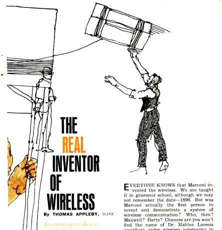
Fifty years ago this month, there was an interesting article about Loomis in Popular Electronics, October 1965, written by Thomas Appleby, W3AX. The illustration above is taken from that article. Appleby was also the author of Mahlon Loomis, Inventor of Radio, published in 1967.
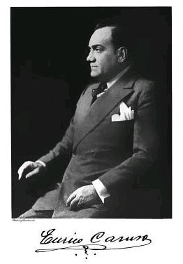
Tenor Enrico Caruso died in 1921, but the January 1938 issue of All Wave Radio magazine noted that the program “The Music You Want to Hear When You Want It,” sponsored by RCA-Victor occasionally carried a “recreated Caruso record” with the voice of Caruso and a recreated orchestral accompaniment. Recording technology had advanced a great deal in the intervening years, as shown by the accompanying photograph of an early recording session, probably taken in the late 1910’s.
In Caruso’s day, it was necessary to record the entire performance thought a single horn. The article explains how the violins were placed near the horn for maximum pickup. The frequency range possible meant that the drums wouldn’t be picked up well anyway, so they were situated near the rear.
The soloist’s voice would, however, be picked up well, and the frequency range of the early recordings faithfully preserved Caruso’s voice. Therefore, it was possible to do a recreation broadcast. Using more modern electronic methods, the orchestra could be picked up well. A new live orchestra accompanied a perfect copy of the old recording for broadcast. The conductor wore headphones, listening to the recording as he conducted to keep perfect time.
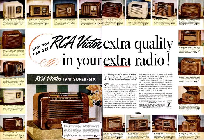
75 years ago today, the October 21, 1940, issue of Life Magazine carried this two-page ad showing what would be some of its last prewar radios, from the company’s 1941 model year. The ad points out that even for your home’s extra radio, you can get RCA Victor quality at a low price, since the models start with the the model 45X-1, later dubbed the “Little Nipper,” for $9.95. This inexpensive set was billed as having, in addition to standard broadcast, “one police band.” A closer inspection reveals, however, that the “police band” means only that it tunes above the standard broadcast band to 1720 kHz, so that police calls in many cities could be heard at the top of the standard AM dial.
Families wishing to tune in to foreign broadcasts with their “extra” set could do so for as little as $19.95 with the model 16X-11, which tuned standard broadcast and one short wave band. Many of the sets featured a “plug-in for Victrola,” meaning that an external phonograph could be added. The least expensive combination radio-phono was the model V-100 for $29.95.
With the end of civilian radio production on April 22, 1942, virtually all of these sets would see service for the next five years, providing war information to their owners.
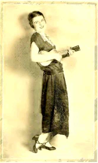
Ninety years ago this month, Radio Age magazine, October 1925, carried this photo of radio star Sally Bell, in what the magazine called an “exceedingly piquant pose.” It notes that she was capturing the hearts of listeners with her eccentric programs with her trusty ukulele. Apparently a California girl, she appeared most consistently on the Hollywood and Los Angeles stations.
A hundred years ago this month, Boys’ Life Magazine carried this ad for a “special station for receiving time signals.” For six dollars, the set included the transformer, loading coil and condenser in a mahogany case. Switches were mounted on the front, with a sensitive cat whisker detector on the top. This set came complete with headphone with silk cord and leather covered headband. The ad reported that other sets were avalable starting at two dollars.
The set was supplied by the S. & K. Electric & Mfg. Co., of 302 Sackett Street, Brooklyn, New York. From the picture, the set appears to be well made, and would undoubtedly pull in the signals from NAA within several hundred miles of Arlington.
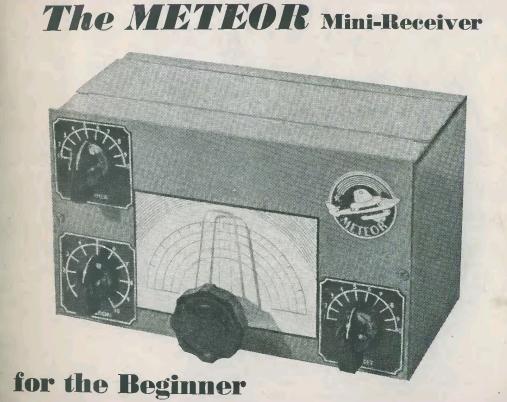
Sixty years ago, the British publication Radio Constructor carried the plans for this simple two-tube receiver in its September, October,
and November 1955 issues. The receiver was dubbed the “Meteor Min-Receiver,” and used an EF41 tube as a regenerative detector, tuning 730 kHz through 32 MHz with the specified plug-in coils. An EL42 was used as a one-stage audio amplifier for driving a pair of headphones.
The receiver was apparently a popular design, since subsequent issues of the magazine carried advertisements from multiple suppliers offering the particular parts that were needed.
In addition to the main tuning control, the three smaller knobs are the antenna trimmer, the bandspread, and the regeneration control. The airplane and “Meteor” logo on the upper right hand corner aren’t a control, as it appears at first blush. That’s simply a decal which was available at a bicycle shop, used to give the little homemade receiver a brand name and logo.
JOTA is an international scouting event which allows Scouts around the world to communicate via amateur radio with other scouts and other amateur radio operators. Our event at the North Star Museum is open to all Scouts, and to the public. It’s free of charge (although we encourage you to also visit the rest of the museum while you’re there, which does have an admission charge.)
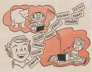
This is the 58th annual JOTA, the first one being run in 1958. The illustration above is from the announcement for the 1959 version, which at the time was called Radio-Jambo. The call signs in the illustration were Scout headquarters stations around the world that were on the air that year.
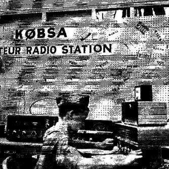
The K0BSA call sign has been connected with the Northern Star Council of the BSA for many years, and I never realized that it had an earlier use. The 1960 National Scout Jamboree was held in Colorado Springs, Colorado, the only time the event has been held in “Zero Land.” There has been Radio Scouting at most, if not all, Scout Jamborees, and in 1960, the official station of the Jamboree was assigned the K0BSA call sign. While the quality of this scan is poor, he Scout shown at the controls of K0BSA in this photo is Steve Wood, K4FJO, of High Point, N.C., who was one of many guest operators of the station. On his QRZ.com profile, K5KG reports that he was on staff at the Jamboree trading post, and spent all of his off hours at the station.
The June 1960 issue of Boys’ Life reported that K0BSA would be operating on all bands from reveille to taps on both phone and CW, with Pedro clomping at the key or braying into the mike.
If you’re in the Twin Cities and have an interest in radio and/or scouting, please stop by and visit. The event is open to Cub Scouts, Boy Scouts, Girl Scouts, and Non-Scouts, which should cover just about everyone. If you’re elsewhere, you can check with your local Scout council. And, of course, if you’re a Ham, please listen for stations calling CQ JOTA and help introduce a Scout to Amateur Radio.
I will also be counseling the Radio Merit Badge. Last year, about 20 Scouts earned the merit badge. “Back in the day” when I was a Scout, the merit badge required a knowledge of Morse Code, meaning that the Scouts who earned it usually did so after getting their amateur license. However, that has changed in recent years, and the merit badge is now more of an introduction to radio. My goal is to get Scouts interested in Amateur Radio, and a few of them have followed up by getting their license. I hope I once again have the opportunity to help Scouts who want to follow up and get their “ticket.”
The war was over, and the American public was hungry for television. A handful of markets already had stations using the same format that would remain in use for seventy years. For example, the predecessor of WNBT-TV came on the air in New York in 1939. And the predecessor of WABD signed on in 1944. And starting in 1942, Los Angeles had the station that would become KTLA. But most of the nation was dark as far as television signals. To get signals to a significant proportion of the populations would require hundreds of stations. And getting network programs to those stations would require either hundreds of microwave relay stations, are a coaxial network estimated to cost a hundred million dollars.
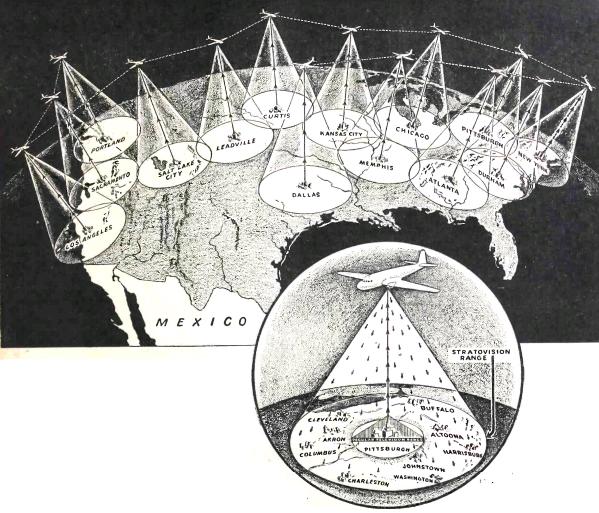
Stratovision provided an alternative. The plan was proposed in 1945 by Westinghouse, and was the brainchild of engineer C.E. Nobles. Under the plan, fourteen aircraft would fly at the predetermined locations shown on the diagram at an altitude of 30,000 feet where they would continually orbit their designated location. They would transmit VHF and UHF television signals, as well as FM broadcasts. Because of the antenna height, each plane would provide a good broadcast signal to an area 422 miles in diameter. And because there would be no terrain that would need to be overcome, the transmitters could operate with much less power than ground-based stations.
The system also solved the problem of delivering network programming. Only eight planes would be required to link New York with Los Angeles. The planes would establish a reliable network whenever they were in flight, and the fourteen planes would provide broadcast television to 78% of the country’s population. The plan called for each plane to broadcast four television and five FM signals.
The plan may appear far fetched to some, but it is sound, and would result in a workable national network. The system was tested by Westinghouse in 1948 and 1949, as seen in this photo. In one 1949 test, the aircraft shown here, a B-29, relayed the signal of WMAR-TV in Baltimore on channel 6, using a 5 kW video and 1 kw aural transmitter. In June 1948, the same aircraft was used to rebroadcast the Republican National Convention in Philadelphia for one hour. As part of the test, a receiver was set up in Zanesville, Ohio, where it was used to demonstrate to the gathered newspaper reporters that the system was capable of reaching small town and farm homes.
Reception reports were solicited, and many were received. From the reports, Westinghouse confirmed that eight planes would provide the transcontinental relay.
There’s nothing technically unfeasible about Stratovision. The reason why it never took off (pardon the pun) was probably the mere fact that broadcast stations did spring up nationwide. They were initially provided with programs by kinescope recordings, but microwave and coaxial transmission quickly came into place. For example, by 1950, the Minneapolis/St. Paul market was getting the national networks live, by means of a coaxial cable from Des Moines, which was in turn linked to Chicago by microwave relay. Once the network signal was in place, there was no need for Stratovision’s relay services. And by this time, most major cities had multiple stations, and smaller markets had at least one. And for those far in the hinterlands, there were herculean efforts to get the distant terrestrial signals, such as those use in the tiny communities of Ellensburg, Washington and Marathon, Ontario.
But despite the fact that Stratovision was never adopted for its intended purpose, it did live on, and continues to do so, in some specialized niches. For example, between 1961 and 1968, educational programs were broadcast from two DC-6AB aircraft based at Purdue University by the Midwest Program on Airborne Television Instruction (MPATI). The MPATI aircraft would fly in a figure-8 pattern for six to eight hours at a time at 23,000 feet above a point just north of Muncie, Indiana. Prerecorded educational programs were broadcast on UHF channels 72 and 76, with call letters KS2XGA and KS2XGD. The transmission diameter was 200 miles, and covered both the Chicago and Detroit metropolitan areas.
Between 1966 and 1972, the U.S. Navy used Stratovision to broadcast two channels in the area surrounding Saigon, South Vietnam. One channel was intended for the Vietnamese audience, with the other providing information and entertainment programs to U.S. servicemen. Armed forces programs were carried on channel 11, with call letters NWB-TV, with the Vietnamese program on channel 9 with call letters THVN-TV. The aircraft also broadcast on 1000 kHz AM and 99.9 MHz FM. The Vietnamese program typically ran 1-1/2 hours per day, with the armed forces channel running three hours per day. American programs included Bonanza, Perry Mason, Ed Sullivan, and the Tonight Show.
Pennsylvania Air National Guard Commando Solo aircraft preparing to depart for emergency broadcasts to Haiti in 2010. Department of Defense photo.
The U.S. military continues to use EC-130 Commando Solo aircraft to provide PSYOPS broadcasts during war. Most recently, only radio programming has been used. But the aircraft is capable of television transmissions. For example, in 1999 in the former Yugoslavia, some television programming, using Yugoslavian broadcast format, was transmitted from aircraft. Typically, Commando Solo transmits an FM program, along with broadcasts on the standard AM band and short wave. For AM and short wave, the airborne transmitter has no particular advantage, other than providing a secure location to house the station. But on FM, the signal, like the original Stratovision concept, takes advantage of the aircraft’s altitude, and can provide a strong broadcast signal over a large area with a relatively low powered transmitter. The photo here shows a Pennsylvania Air National Guard Commando Solo aircraft preparing to depart for Haiti to make emergency broadcasts in the wake of the 2010 earthquake.
During the 2011 attack on Libya, Commando Solo aircraft broadcast information. Transcripts of the broadcasts are available at PsyWar.org. Since the Libyan broadcasts were carried on short wave as well as FM, they were heard by short wave listeners worldwide, including myself. A recording of the transmissions can be found at this video:


 , published in 1967.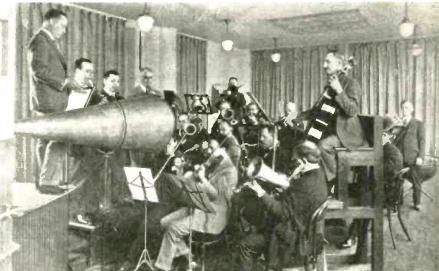


 The plan may appear far fetched to some, but it is sound, and would result in a workable national network. The system was tested by Westinghouse in 1948 and 1949, as seen in this photo. In one 1949 test, the aircraft shown here, a B-29, relayed the signal of WMAR-TV in Baltimore on channel 6, using a 5 kW video and 1 kw aural transmitter. In June 1948, the same aircraft was used to rebroadcast the Republican National Convention in Philadelphia for one hour. As part of the test, a receiver was set up in Zanesville, Ohio, where it was used to demonstrate to the gathered newspaper reporters that the system was capable of reaching small town and farm homes.