Category Archives: Radio history

Canadian Northern Radio

1942NovManitobaCallingSeventy-five years ago this month, the cover of the November, 1942, issue of Manitoba Calling, the program guide of CKY Winnipeg, carried this photo of two northern residents being kept company by their radio through the lonely winter.

With its 15,000 watt voice from Winnipeg, the station had become “one of the family” for many of those in Canada’s north, including missionaries, trappers, Mounties, doctors, nurses, and fur traders.

The magazine noted that during the First World War, many of these residents did not hear until the spring of 1915 that Canada was at war. But with radio, “a fur trader in his lonely cabin will hear the news and the latest developments on the war-fronts at the same instant that we in urban centres hear them.

The article noted that radio must still occasionally bow to atmospheric conditions, and the Aurora Borealis might occasionally wreak havoc on the standard broadcast band. But it also noted that when broadcast reception was poor, shortwave reception was frequently good, allowing northern residents to hear both American and overseas stations.

The service provided by CKY continues as part of CBC North.  While shortwave service ended in 2012, service is currently provided by a network of FM stations.


Ship Radio Operators Needed: 1967

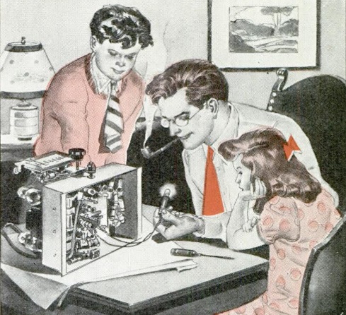
1967NovEIFifty years ago, the November 1967 issue of Electronics Illustrated explained how the gentleman shown in this drawing could achieve his dream of seeing the world as a ship radio operator.

The article made clear that there were two conflicting priorities at work: The lines needed radio operators, but the unions had their own vested interest in keeping the supply tight.

Ships sailing under the American flag had to have a licensed radio officer aboard, and the lack of men sometimes meant sailing delays. One bottleneck was Vietnam. Two hundred ships had been called up from the reserve fleet. Many radio officers had been called back from retirement, and those on duty were being asked to forego vacations and leave.

Entry into the field wasn’t easy. Most American ships carried only one radio officer, but he had to hold a First Class license. But to get a First Class license, you had to have six months’ service at sea.

Because of the shortages, the Radio Officers Union recently started a limited training program. After six months, the man was ready to take an assignment on a one-man ship. After 18 months, he was entitled to full membership in the union. Base pay was $300 per month for the next six months, and then $600 per month for the next 18. After becoming a full member of the union, his pay shot up to $900-$1000 per month, with good benefits. Retirement, with about a third of the pay, was possible after just 20 years of service, regardless of age.

The magazine contained addresses of the union and companies for those interested in looking into a career at sea.


1937 Ground Rod and AC Powered Mini Trouble Lamp

1937NovPMEighty years ago, the November 1938 issue of Popular Mechanics showed this method of increasing your ground conductivity. The addition of water isn’t even mentioned in the text. But by adding the water, the ground near the rod becomes saturated, increasing the conductivity.

The actual hint being discussed is the use of a spark plug as a lightning arrestor. The lead-in is connected to one terminal of the spark plug, with the other end grounded.

1937NovPM2Another hint shown in the same issue is shown here. Batteries are cheap enough these days that I don’t think it would be worth trying to put together this contraption, which doesn’t look very safe. But if you really want to run your small flashlight off AC power, then wiring it in series with a 25 watt light bulb, as shown, would do the trick.


1937 Midget One Tube Regen

1937OctPS1The November 1937 issue of Popular Science carried the plans for this midget one-tube regenerative receiver for the broadcast band using a dual-grid type 49 tube.  The notable feature of the tiny set was that it employed only a single battery, a 3 volt “A” battery that powered the filaments as well as supplying the modest B+ voltage.

The low power requirement apparently meant that the set was just a bit finicky, since the article cautioned that many of the parts had to be exactly as specified in the article.  But when done, the midget tube set was said to produce good headphone volume with 10-20 feet of insulated wire tossed on the floor as the antenna.

The modest battery requirement meant that the set was ideal of hikers and campers, or for use in isolated areas without electric power.


1937OctPSSchematic

Midget tube receiver schematic


Ying Ong, American Radio Patriot

1942NovRadioCraftShown here in the November 1942 issue of Radio Craft is Ying Ong of Phoenix, Arizona, rightly described by the magazine as an American radio patriot.

Mr. Ong took it upon himself to listen to and transcribe the broadcasts from Chungking Radio. He took the contents down by shorthand, and then relayed them to his fellow Chinese-American countrymen and to American news services. His dispatches often were made by telegram, and he bore the expense himself. He also sent copies to the FCC, Chinese-American newspapers, and the Chinese consulates.

The nationalist Chinese government took note of this, and at one point sent him a check for $100 to help cover his expenses. He endorsed the check over to the China War Relief Fund.

The broadcasts of the powerful GE San Francisco shortwave station KGEI often, the magazine noted, contained in its newscasts the phrase “Chungking radio says….” These reports were able to hit the air so quickly thanks to Mr. Ong’s transcripts of the broadcasts.

I was not able to find a listing for Mr. Ong in either the 1940 or 1946 call books, so I don’t believe he was a licensed ham.  But as an SWL, he certainly performed a service to both China and America by ensuring that nationalist broadcasts were received in this country by all who needed to hear them.

According to the Social Security Death Index, a Ying Ong, born on 25 August 1918, with a place of residence in Phoenix, died on 17 July 1992. He is buried at Greenwood Memory Lawn Cemetery in Phoenix.


1947 Two-Tube Regen for Junior

1947NovPSWhile this project from the November 1947 issue of Popular Science is ostensibly a Christmas present for Junior, the text of the construction article reveals that Mom and Dad might have an ulterior motive:  “Everyone in the family will enjoy this little two-tube headphone set.  Junior can listen to all the programs especially meant for him, and Pop and Mom will escape the nerve-shattering tommy guns and thundering herds.”

The set is a two-tube regenerative receiver for the broadcast band, using a 12J7GT detector with a 12J5GT serving as audio amplifier.

It’s an AC/DC set, meaning that Junior should probably make sure he doesn’t use it close to the water pipes. It appears to be electrically isolated from the chasis, and as long as capacitor C8 doesn’t short out, the headphones will be isolated from the AC line.

To tame the regenerative receiver, and keep Junior from becoming a squeal hound, the controls are preset, and tuning is accomplished with three or four trimmer capacitors set to local stations, and a switch is used to pick the station.

No external ground is used (probably to keep the AC-DC set from blowing a fuse or zapping Junior). The article notes that an outdoor antenna is desirable but not absolutely necessary.


1947NovPSschematic


1957 Springfield Enterprises VHF Transceivers

1957NovPEThis ad from sixty years ago, in the November 1957 issue of Popular Electronics,  was for two little VHF rigs I had never seen before, from a company called Springfield Enterprises of Springfield Gardens, New York. The prices shown in bold print certainly look reasonable. The two-meter version is priced at $6.98, and the six-meter version is $14.98. But the fine print reveals that these are the prices for the chassis only. It is already assembled, but it doesn’t include the microphone, “miniature mike transformer,” headphones, or even the case. With these “accessories,” the price increases.

The description is lacking in details, but the two-meter version is a single tube with VFO. It’s probably similar to the transceiver shown previously at this link.

The six-meter version contains a crystal-controlled transmitter with variable frequency receiver, and uses multiple tubes. Both sets were billed as having a range of 1-5 miles with a built-in whip, and “much more with directional beam antenna.”

I’ve never seen any reference to either of these rigs, other than this K3DSM’s website, in which he states that he owned one of the two-meter versions.


1947 One Tube Matchbox Radio

1947OctPS1Seventy years ago this month, the October 1947 issue of Popular Science carried the plans for this simple one-tube receiver mounted on a chassis the size of a matchbox.

The set used few parts beyond the 1S4 tube. Tuning was accomplished by a 175-500 pF trimmer capacitor. The article noted that the small capacitor might not cover the full broadcast band, but suggested small plug-in coils to extend the range.

The set required a 1.5 volt battery for the filament, in addition to a B battery, which could be as low as 4.5 volts.


1947OctPS2


Roy Gould, W6UKX, KFXM Engineer & Engineering Professor

1942Oct26BCSeventy-five years ago today, the October 26, 1942, issue of Broadcasting carried this picture of the transmitter engineer of KFXM, San Bernardino, California, who appears to be dutifully taking some transmitter readings for the log.

Because of wartime labor shortages, the engineer responsible for keeping this station on the air was a fifteen year old high school student, Roy Gould, W6UKX.  (A few days ago, we saw how wartime labor shortages led a group of New York radio servicemen to train high school students to keep their shops open for the duration.)

Gould had received his ham ticket shortly before Pearl Harbor, and had managed to get on the air, with a homemade transmitter and receiver on 10 meter AM, before the war shut down amateur radio for the duration.

Since Gould also held his first class commercial license, he managed to stay on the air by getting a job at the broadcast station, which was at the time running  100 watts at 1240 kHz, sharing air time with KPPC, a Pasadena Presbyterian Church station.

According to the caption of the photo, Gould’s plans after the war were to go to college to “become a radio engineer.”

I was able to track down Mr. Gould–or I should say Professor Gould–and learn that his plans changed somewhat, although his early days in radio were clearly the inspiration for his career.  I received a nice e-mail from him, and also found a 1996 Oral history interview.

In his e-mail, he writes:

Thanks for the links, I have never seen this picture.

I remember those days well. I used to operate the transmitter and on Sunday evenings, record a Mutual Don Lee network program on the big 16″ acetate covered disks for replay at a later time. There was no announcer in the studio on Sunday evenings so I even signed the station off at the end of the day. I also covered remote broadcasts of some of the big bands at the San Bernardino Civic Auditorium, setting up microphones and operating the control box during the broadcast.

I got my ham license W6UKX in early 1941, and did a little operating before WWII shut down ham radio. I let it lapse in the 1950’s when I was in graduate school. However, that call sign was never reissued, so I was able to get it back under the vanity call sign program in the 1990’s. I have a web page, w6ukx.caltech.edu, but for some reason it Is down now. I’ll look into that. [Here’s the 2015 archived version at the Wayback Machine.]

Thanks again for the great photo with the short note. 73.

Roy

Roy W. Gould

Prof. Roy Gould. Caltech photo.

Gould never became a “radio engineer”.  According to his biography at Caltech, he received his undergraduate degree from Caltech in 1949, with graduate degrees from Stanford and Caltech.  He became Professor of Electrical Engineering and Physics at Caltech, and served a stint as the chairman of the school’s Division of Engineering and Applied Science.

According to his Wikipedia entry, he received the 1994 James Clerk Maxwell Prize for Plasmaphysics, and served as the Director of Fusion Research at the Atomic Energy Commission.

In his 1996 interview, Gould credits his early radio experience as the seed for his career.  He reports that in high school, he was “not a very good student.”  But his uncle’s barn was full of old radio equipment and magazines, and he “used to go up there and read these things and look at the equipment, play with it and stuff like that.  I got started in electronics with crazy experiments.”  Of course, we are also advocates of crazy experiments, and students seeking inspiration will find ideas, some crazier than others, in our science fair idea posts.

The shortage of broadcast engineers meant that he was able to get the job at the radio station, which he reported as being more interesting than was going on in school.

The broadcast station where Gould got his start, KFXM, doesn’t appear to be around in its original form.  However, the station and call letters live on as a noncommercial low-power FM station, KFXM-LP.  The old AM station appears to have been a major Top-40 outlet during the 1960’s, and when it went dark, the low power FM station was licensed to The Organization For the Preservation & Cultivation of Radio to carry on the tradition.

After letting his license lapse during grad school, Gould got his ticket after achieving emeritus status, and is again active on HF, including a number of portable DX operations detailed at his website.


1967 Hart-65 One-Tube Transmitter

1967OctPEHart65Readers of this blog might remember the name Hartland Smith, W8VVD, currently licensed as W8QX.  We previously featured his steam powered transmitter, which appeared in Popular Electronics in 1965.  A number of his projects appeared in PE and other magazines, and the one showed here appeared in Popular Electronics 50 years ago this month, October 1967.

It was a transmitter for the novice which put out a very respectable 65 watts on 80 and 40 meters. It was an updated version of the author’s “Hart 25” transmitter which appeared in the magazine in 1955. Despite the increased power, the new version boasted the same price of about $20 for all of the parts.  The 1955 version had used a 6W6 tube to put out about 25 watts, along with a 5Y3 rectifier in the power supply.

The 1967 version employed a 6HB5 TV horizontal amplifier, which was said to be highly efficient at cranking out RF. Tuning was accomplished by the simple expedient of tuning the pi network for maximum brightness of the pilot lamp. Another pilot lamp was provided for monitoring the current to the crystal, since too much current could fracture it. The article noted that smaller HC6/U crystals (and almost any modern crystal designed for solid-state circuits) should not be used because they would overheat, drift, and possibly shatter.

Cathode keying was used, but since the would mean as much as 700 volts across the key, a 6 volt relay was used for safety. The built-in power supply used a semiconductor bridge rectifier.

Smith recommended a full-size dipole antenna for the transmitter, rather than trying to use it with a random wire or multi-band antenna. He did have one insight that I independently discovered years later: “If an 80-meter dipole is too long for your piece of real estate, don’t hesitate to bend it around corners, or even droop the ends. Whatever the final arrangement, make certain that you have a total of 125′ of wire in the air.”  As you can see from my fan dipole from the June 2010 issue of QST, I’m not adverse to introducing a few zig-zags into an 80 meter dipole in order to squeeze it only a city lot.

He notes that the pi network should be adequate for keeping harmonics to a minimum. However, he also advises that if TVI is a problem, a low-pass filter in line with the antenna is in order. With today’s more stringent requirements for spectral purity, it would probably be a good idea to add the extra filtering even in the absence of TVI reports.

He reported that on the air, he worked numerous stations throughout the U.S. and Canada on both 80 and 40 meters. The rig had a “click-free pure d.c. note that was a joy to copy.” It was reported to be “rock-steady” on 80 meters, and “its 40-meter stability compares favorably with that of many low-cost VFO transmitters presently on the market.”

1967OctPEHart65Schematic

Hart-75 Transmitter. QST photo.

Hart-75 Transmitter. QST photo.

In addition to writing articles, Hartland Smith was the proprietor of Hart Industries, which produced a number of kits (and a few wired sets), including the Hart 25.  The 1955 Popular Electronics article included the address for Hart Industries for the kit, which included the pre-punched chassis.  Another Hart Industries kit was the similarly named Hart-75 from 1956. That transmitter was reviewed by Lew McCoy, W1ICP, in the February 1956 issue of QST. Even though the basic circuit was quite different from the PE transmitter (it used a 6AG7 oscillator and 807 final), it did have one common design feature, namely, the use of the relay for keying.

The 1956 model had an interesting twist, in that a DPST relay was used, keying the oscillator and amplifier almost simultaneously. But the circuit used something called “differential keying.” The contacts of the relay were set so that the oscillator came on slightly before the amplifier, and stayed on longer. The result was that chirp was greatly reduced.