Category Archives: Radio history

Three 1943 One-Tube Receivers

1943JanRadiocraft1

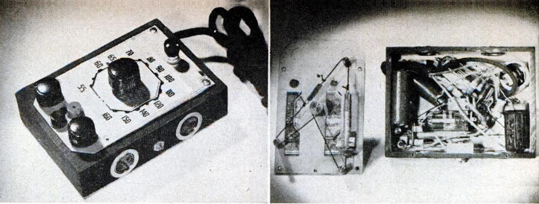
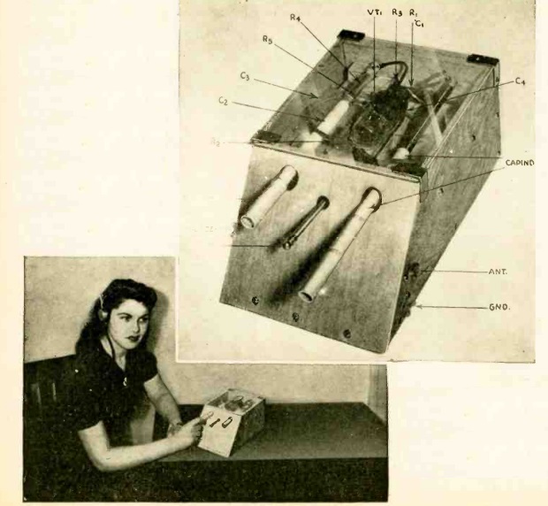
The January 1943 issue of Radio Craft magazine contained the plans for no less than three one tube receivers, the first of which is the unusual looking set shown above, dubbed by the magazine as the “Simplicity 1.”

In addition to being designed around the concept of simplicity, the set dealt with parts shortages. In particular, variable capacitors were hard to come by. Therefore, tuning was accomplished with a “capind,” a component which combined capacity plus inductance. In other words, it was a combined variable capacitor and variable inductor, all in one component.

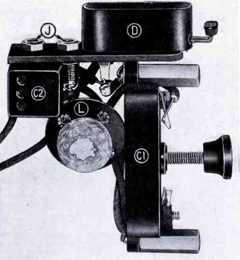
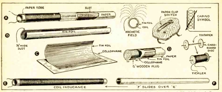
The “capind” consisted of a coil carefully wound over a wooden dowel, covered by an extremely thin paper sleeve. That was covered by a piece of tin foil, which served as the capacitor. The assembly is shown below:

1943JanRadiocraft2

1943JanRadiocraft3
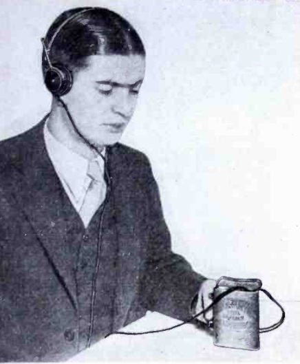
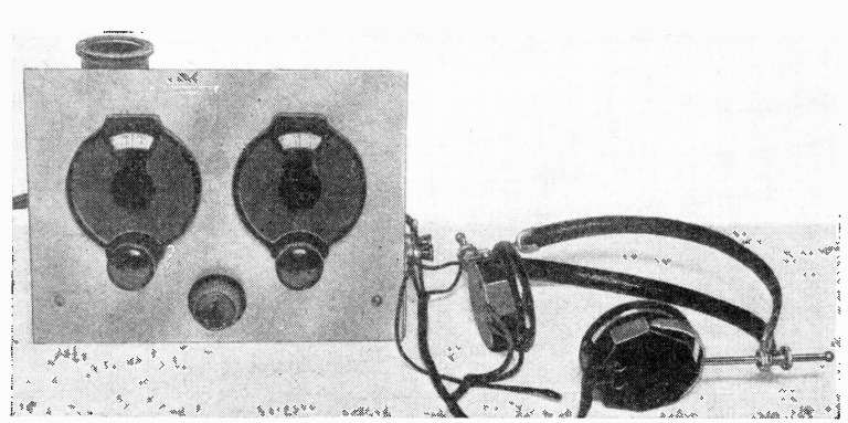
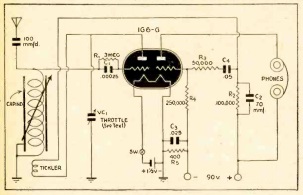
The set was regenerative, and the young woman in the photo above is adjusting the regeneration by adjusting the “throttle” condenser, which is a homemade tubular capacitor.

With the use of these homemade parts, the cost of the set (not including 1G6G tube and batteries) was said to be less than a dollar.

1943JanRadiocraft4
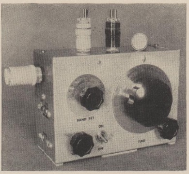
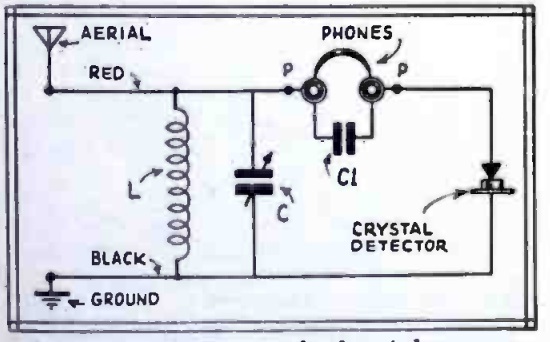
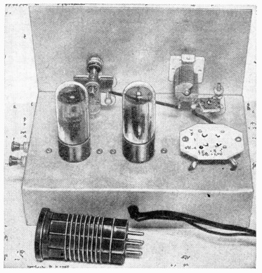
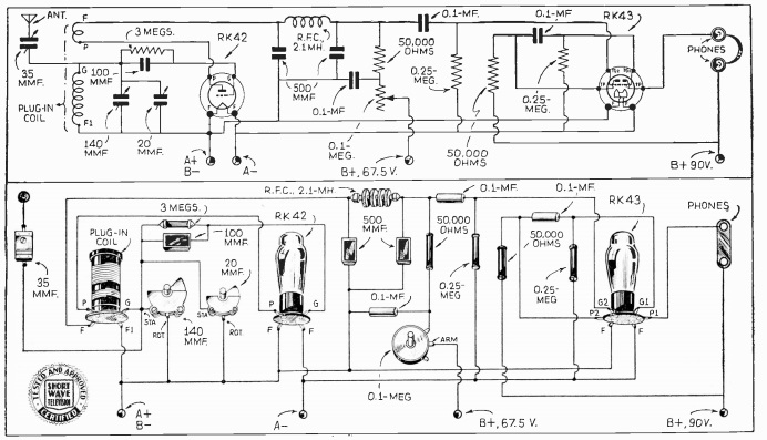
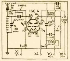
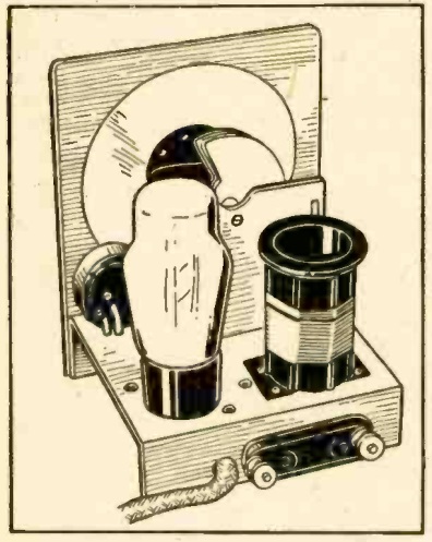
The second set featured by the magazine, shown at right, is slightly more advanced, contains a conventional tuning capacitor, and was capable of tuning the short wave bands through the use of four plug-in coils.

This set employed the same 1G6G tube, and used a variable resistor to adjust regeneration.  The use of a 35-75 foot antenna was recommended.

1943JanRadiocraft5


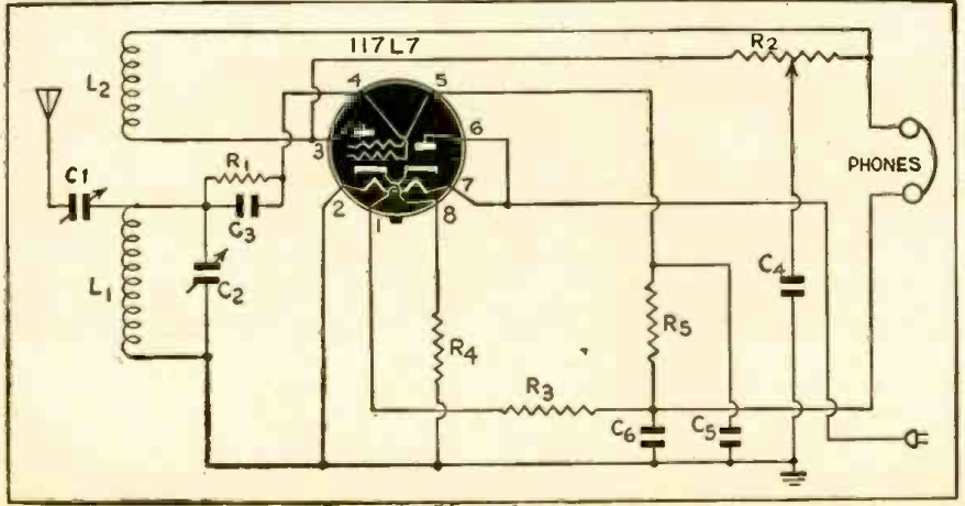
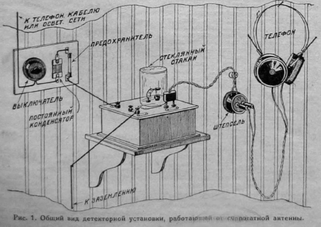
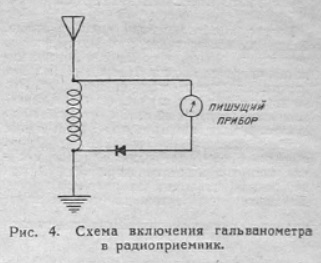
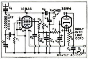
Finally, in response to requests by “several readers,” the magazine reprinted the schematic of the “Pigmy Receiver” which had originally appeared in the magazine’s June 1940 issue. This set used a single 117L7, one half of which served as rectifier, with the other half serving as detector.

You will note that only one wire is connected to the line cord, which the magazine describes as a “Safety First” method of plugging it in. The other power connection is through the thoroughly grounded chassis. With the cord plugged in the wrong way, the set would not light. Of course, this circuit would trip a modern ground fault interrupter circuit, but it would be a relatively safe way of operating a radio directly off the line current.

1943JanRadiocraft6


1958 Boys’ Life 3-Transistor Regen


1958JanBL1958JanBL1The January 1958 issue of Boys’ Life magazine carried the third part in a series about shortwave listening, and included the plans for the three-transistor shortwave receiver shown here. The construction article was authored by Howard McEntee, W2SI, who was also the designer of the magazine’s 1956 CONELRAD receiver.

The shortwave set covered 1.25 to 18.5 MHz with four plug-in coils, meaning that it could tune the top of the broadcast band, several shortwave broadcast bands, and the 160, 80, 40, and 20 meter ham bands.  It employed a 2N1114 as the regenerative detector, followed by two CK722‘s for audio amplification to drive a pair of headphones.  It was powered by four penlite cells, which were said to provide several hundred hours of use.

Tuning was accomplished with two variable capacitors, one for broad tuning, with another for bandspread for carefully tuning a crowded band.  A third variable capacitor was used to adjust regeneration.

The article cautioned that this set wasn’t necessarily for beginners.  It advised that those who had never built a radio before should start with a more simple set and then graduate to this one.  “Real care is needed in wiring, for a wrong connection in some parts could mean immediate ruin of over $10 worth of transistors, the finished job shoujld be checked and rechecked, before the power is turned on.”


1958JanBL2


1952 and 1954 Solar Eclipses

SovietEclipseCoverMillions of Americans were able to witness the Great American Eclipse of 2017 or will be able  to see the eclipse of April 8, 2024.  The 2017 eclipse crossed the United States from northwest to southeast, and the 2024 eclipse will run from southwest to northeast.  The Soviet Union had a similar pair of eclipses on 25 February 1952 and 30 June 1954.  The intersection of the two American eclipses is near Carbondale, Illinois.  The paths of the two Soviet eclipses had their intersection at a point in northern Iran, just south of the Caspian Sea.

SovietEclipseMap

The illustrations shown here are from a Soviet booklet published in 1950.  In addition to discussing solar and lunar eclipses generally, it contains information about the two Soviet eclipses of the 1950’s, including the map shown above.  It also contains a table showing all total solar eclipses worldwide through 1999.

The booklet, Солнечные и лунные затмения (Solar and Lunar Eclipses) by Prof. A.A. Mikhailov, part of the series Научно-популярная библиотека (Popular science library), reveals that the path of the 1954 eclipse came very close to a number of Soviet cities, including Kaliningrad, Vilnius, Minsk, Kiev, Rostov, and Baku.   The 1954 eclipse had also been visible in the United States, starting at sunrise in Nebraska, and passing over South Dakota and Minnesota (including Minneapolis and St. Paul).  It then passed over Canada, Greenland, a tiny portion of Iceland, Norway, and Sweden, before entering the Soviet Union near Kaliningrad.

The 1952 eclipse, after passing over Africa, went over a less populated area of Turkmenistan, Uzbekistan, Kazakhstan, and Asiatic Russia.

This video shows the 1954 eclipse from Minneapolis:

This page contains a reminiscence and photo of the same eclipse from Kiev.  The Google translate function does an admirable job of making it readable in English.

One of the scientific observations made during the 1954 eclipse was the measurement of radio emissions by the sun on various frequencies, documented in this 1955 article in the journal Astrophisica Norvegica, vol. 5, p. 131.  The graph below shows the signal as received in Vesterøya, Norway, on 200 MHz.  As would be expected, the solar noise reaches a minimum value at the time of total eclipse.

1954EclipseRadio

Information on how to form a Minnesota LLC.


1933 Crystal Set with Piggly Wiggly Detector

1938JanTVNews

1938JanTVNews1Shown here is a very basic crystal set mounted in a tobacco can, as shown in the January 1933 issue of Television News.

The design for this well-constructed little set apparently originated in a Danish magazine, and was adapted by one Clifford E. Denton, who put it together in a couple of hours one evening. The variable capacitor, shown as C1 in the close-up picture here, was a compression type. The plates did not rotate. Instead, the screw was turned to compress the capacitor, with an insulating material to keep the plates from shorting out. This component was known as a “variodensor.” The coil could be purchased, or made at home on a wooden form.

The most notable feature of this set was the fixed detector, bearing a brand name that apparently never quite made it in the world of radio. The detector was a “Piggly Wiggly crystal detector.” The magazine described the Piggly Wiggly as “much better than the old-fashioned open detector, the crystal itself and the cat-whisker being enclosed in a neat molded bakelite case.” It could be adjusted by means of a “little red button” on the outside.

1938JanTVNews2


1928 Soviet Crystal Set & Galvanometer Experiments

1928No1RadioLThis illustration of a handsome crystal set listening post comes from 90 years ago, in 1928 issue number 1 of Радиолюбитель (Radio Amateur) magazine, illustrating an article by A. Pushkov.

Elsewhere in the magazine, it’s apparent that, just like their Western counterparts, young Soviet experimenters discovered the fun that could be had with a milliammeter, although I have to admit that I never thought to conduct the second and fourth experiments shown here:

1928No1RadioL11928No1RadioL2

(The piece of metal in the above diagram is marked “железо”, iron.)

1928No1RadioL31928No1RadioL4

The sensitive galvanometer was probably a valuable instrument in the 1928 Soviet Union.  Modern students desiring to reproduce these experiments can do so very inexpensively with a digital voltmeter such as the ones shown here:


1944 Toy Phonographs

1944SearsToyPhonoI was a little bit surprised to see these phonographs for sale in a wartime catalog, but they are shown here in the 1944 Sears Christmas catalog.

They’re surprising for a couple of reasons.  First, they’re an interesting juxtaposition of an acoustic phonograph with an electric motor.  I assumed that acoustic phonographs were wind-up models, and that electronic phonographs had an electric motor.  But there’s no reason why there can’t be some overlap..

But I was more surprised to see phonographs for sale, despite the fact that the manufacture of phonographs had ended by order of the War Production Board (WPB) on April 22, 1942.  It’s unlikely that there was much old stock left in the Sears warehouse at that point (although it’s not at all unlikely that there were electric phonograph motors left over when the ban went into effect).

Interestingly, these are not being sold as phonographs.  They are being sold as toy phonographs.  I’m not aware that the WPB made an exception for acoustic phonographs.  But apparently, they did make an exception for toy phonographs.

The model on the right looks like a toy, especially with the decorations.  But the model on the left doesn’t really look like a toy.  It looks more like just a low-end portable phonograph.  I suspect that more than a few were sold, not for the kids, but because it was the only new phonograph people were able to buy.

The video below shows a similar instrument manufactured, surprisingly, as late as 1974:


The DX Hounds Are Back, 1948

1948JanBLSeventy years ago this month, the January 1948 issue of Boys’ Life magazine let its readers know that after a wartime absence, amateur radio was back, and that the DX Hounds were back. The article began with the story of how an Ohio ham, former Navy radio operator Paul L. Hughes, saved 300 in New Mexico. One night, Hughes heard a call on 10 meters from a motorist stranded in a snowstorm with 300 other motorists in New Mexico. Hughes found a ham in Albuquerque who phoned the New Mexico State Police, who had a rescue party on the way 26 minutes after the call for help.

For scouts interested in getting started, the article recommended three books, How to Become a Radio Amateur and the License Manual from the ARRL, as well as, of course, the Radio Merit Badge pamphlet. Each was available for 25 cents from the respective publisher.


1948 Permeability Tuned Receiver

1948JanPS1Even though the war was over, it appears that aluminum was still in somewhat short supply, or at least expensive, in 1948, since it’s not unusual to see radios from that era using permeability tuning, which means that a variable capacitor was not required.

1948JanPS2Here’s one such example from the January 1948 issue of Popular Science. This little one-tube set uses a 12BA6 as a regenerative detector, with a 35W4 rectifier and “curtain burner” cord to run the filaments.  Tuning is accomplished by moving a slug through the coil, changing the inductance.  The complete coil assembly was  available as a commercial part, and was listed on the parts list as merely a “permeability tuning unit for regenerative circuit.”

The accompanying article didn’t include an explanation for hooking up the dial string, since the entire assembly was commercially available, and the other parts were simply squeezed in.


Eunice Johnson, KOA Denver

1928JanRadioDigestShown here on the cover of the January 1928 issue of Radio Digest is Eunice Johnson of KOA Denver, described as “the most beautiful artist” in radio.  According to the magazine, she was “still in her teens, but she sings and talks to her audience like an old timer.”

The GE station signed on in 1924 with 5000 watts, increasing to 12,500 watts in 1927.  It went to its current power of 50,000 watts in 1934.


1938 Two-Tube Regenerative Receiver

1938JanSWTV11938JanSWTV2Eighty years ago, the January 1938 issue of Shortwave and Television magazine carried the plans for this two-tube regenerative shortwave receiver.  With plug-in coils, the set would cover 550 through 9 meters. The set used two 1.5 volt tubes: The RK42 triode served as regenerative detector, and a dual RK43 provided two stages of audio amplification.

The set was capable of pulling in stations from around the world, and “there is practically no limit to which this receiver will cover. So long as general receiving conditions are favorable, this little set will work wonders.”

The use of two variable capacitors allowed for bandspread tuning, and a variable resistor was used for regeneration.

1938JanSWTV3