Category Archives: Radio history

Two 1940 Broadcast Sets

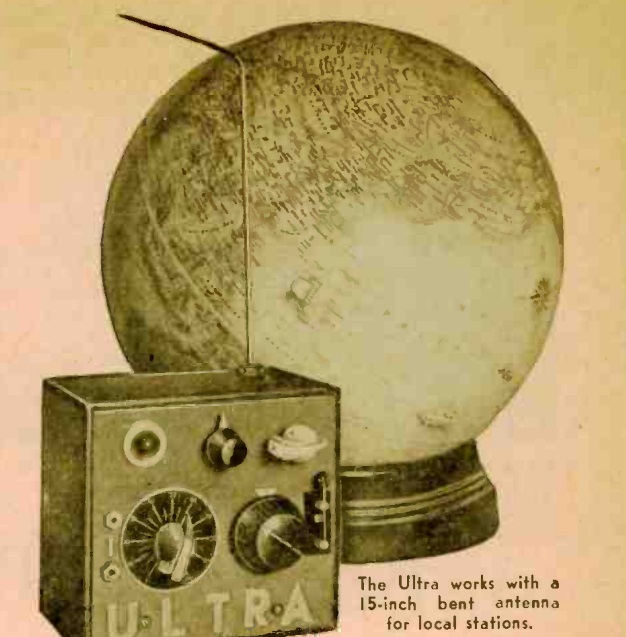
1940JanPS1940JanPS2This young woman is getting ready to tune in a favorite program, thanks to the radio designed to look like a book, described in the January 1940 issue of Popular Science. The design was intended to “appeal to all builders who prefer housing their receivers in some unusual type of cabinet.” It was perfect for the library table, where it would make an attractive decoration while pulling in the local stations.

The cabinet was constructed with the covers of a scrapbook purchased for less than a dollar. The jigsawed decoration on the cover was retained, and sides were build from matching wood. The circuit itself was a two-tube regenerative receiver. It ran directly off line current, with the filaments voltage provided by a “curtain burner” cord.

1940JanPS3

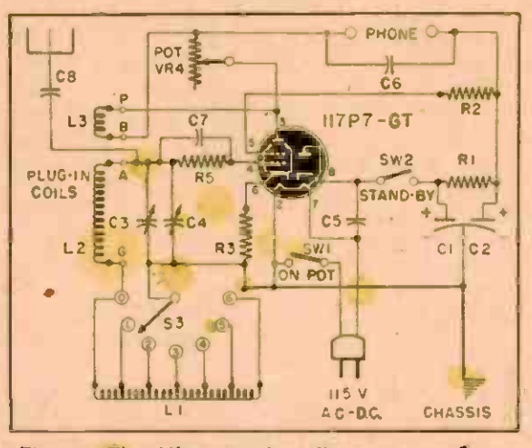
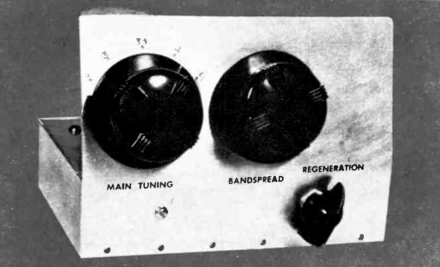
For those seeking a compact but more conventional design, the same issue of the magazine1940JanPS4 showed the design at right. It was a three-tube regenerative set featuring a small two inch speaker.  Like the book radio, it covered the broadcast band.  It was also an AC-DC set, with the filaments in series powered by the ubiquitous curtain burner.

1940JanPS5


1939 Transmitter and Receiver Kits

1939AlliedCatalogXmtrEighty years ago, the newcomer to amateur radio could get on the air with this transmitter kit from the 1939 Allied catalog.  It was patterned after the transmitter shown in the ARRL publication How to Become a Radio Amateur, and used two type 47 tubes running push-pull. The set could be put together in about two hours, and would put out up to 10 watts on 80 meters.

The cost of the kit itself was $2.60, but it wasn’t quite ready to go. The accessory kit included the 1939AlliedCatalogRcvrtwo tubes, a crystal, and key. If the beginner was lacking all of those items, that would be an additional $4.80.  If the new ham already had a commercial receiver, then he could probably tap into the power supply to run the transmitter. Otherwise, the power supply would be an additional $5.35, for a grand total of $12.75.

If he didn’t have a receiver already, then the bare minimum would be the kit shown here on the same page. The kit, using a single type 30 tube, cost $4.45. The tube and battery would be an additional $1.75. The coils that came with the radio covered the broadcast band, so getting on the ham bands would also require the shortwave coils, for 85 cents.


Christmas 1919

1919XmasMerry Christmas from OneTubeRadio.com!

This photo establishes conclusively that Santa Claus has been placing radios under the tree for a full century, since the photo was taken on Christmas, 1919.

Shown is the family of U.S. Secretary of War Newton Baker. From left to right are his daughter Betty  (Elizabeth Baker McGean), son Jack (Newton D. Baker, III), daughter Peggy (Mrs. Fulton Wright), and wife Elizabeth. The younger children were obviously extra good that year, since Peggy is shown playing her Schroeder-style toy piano, and was probably also the recipient of the doll bed shown in the background.

1919XmasRadioBut young Master Jack had obviously been very deserving, since Santa brought him a radio! Not only was he probably the first on his block (child or adult) to have a radio, it was probably one of the first ever received as a Christmas present. The wartime ban on private radio receivers (presumably ordered by his father) had only ended on April 15 of that year.  (The transmitting ban ended on October 1.)

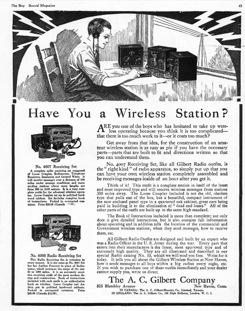
The site from which this picture is taken, Shorpy.com (see more information below) has a high-resolution copy,which allows more detail of the radio to be seen. Unfortunately, there’s not enough to be able to positively identify the set, but it does appear to be a fairly high-end crystal 1920JanElecExpset, not unlike the A.C. Gilbert model 4007 shown at the right (from the January, 1920, issue of Electrical Experimenter).  According to another ad for that set, the list price was $25, and it was said to have a range of 200 miles.  The one in the picture looks comparable.  Since Master Jack lived right in Washington, he certainly would have been able to pull in the strong signals of station NAA in Arlington. Of course, any voice modulation was extremely rare at that time, so he would need to sit down and teach himself the code. And he wouldn’t hear anything with the set under the tree, since it doesn’t appear to be hooked up to antenna and ground. But since he was right in Washington, only a modest antenna would have been required to pull in the powerful government station. So I suspect he was hearing sounds out of the headphones Christmas night.

Shorpy.com

The image above is courtesy of Shorpy, an amazing archive of thousands of historical American photographs from the 1850s to the 1950s. The Washington Post describes the site as one which offers a chance to time travel. We hope the same can be said about OneTubeRadio.com. As you celebrate Christmas today, enjoy this opportunity to visit a young radio listener a century ago. If you gaze closely enough at the photo, perhaps you’ll be able to hear the buzz of NAA’s arc coming through those headphones.


1930s Five Meter Transceiver

Uncle Jim Pearson with van

I received an interesting e-mail from Bob Miller, the nephew of the gentleman shown above, Jim Pearson of Townsville, Queensland, Australia. As you can see from the truck, he worked in the 1930s as a radio serviceman for Connolly’s Radio. According to this 1945 ad, the company was located at 128 Flinders Street.

According to the truck, the company sold Stromberg-Carlson radios. The American company started its Australian subsidiary in 1927 by importing American sets. But the subsidiary, Stromberg-Carlson (Australasia) Pty. Ltd., was autonomous, and soon began manufacturing its own sets for the Australian market. The McClary Electric Stoves advertised on the truck were possibly similar to this one.  Stoves by that name were also made in Canada.

Uncle Jim's diagramPearson was killed in action in RAF Bomber Command in 1942. The reason I was contacted is the schematic shown at left, which was found in Pearson’s effects. For a larger version, from most browsers, click twice on the image. Miller correctly guessed, probably from the presence of both a microphone and headphone, that the circuit was for a transceiver.

The size of the main coils is specified as 5 turns, a half inch long, with an inside diameter of a half inch. This led me to believe that it was for VHF, either 5 meters or 2-1/2 meters. We’ve previously shown similar circuits for amateur and WERS transceivers, such as this one, this one, and this one. Some of those circuits have two tubes, the second one being an audio stage used both transmitting and receiving. But they all employed the same simple idea–a single tube is used for a transmitter, and by switching a few components around, as a superregenerative receiver.

But something looked very familiar about this particular version. I did a little more digging, and realized that we had previously shown an identical circuit, the schematic shown here. The circuit was the design of Stanley Johnson, W9LBV (later W0LBV), of Grand Island, Nebraska, and appeared in the December 1935 issue of Popular Science.

The diagrams and parts specifications for the two sets are virtually identical, so the Pearson drawing must have originated with the Popular Science article. The only difference is that the article uses a type 76 tube, but Pearson’s diagram calls for either a 56 or a 76. The two tubes appear to be identical, with only the filament voltage being different. Perhaps the 56 was easier to find in Australia.

Johnson, the American author, went on to write a number of other construction articles over the years, such as a novice transmitter in the October 1951 issue of Popular Mechanics.  He died in 2003.

Miller didn’t know whether Pearson ever got his ham ticket or if he ever built the radio.  I checked the 1938 callbook listings for Queensland, and didn’t see any listing under his name.   Perhaps he was licensed elsewhere, or perhaps he planned on getting his ticket after the War.  That, of course, never happened, as his life was cut short by the War.

One of the reasons why Amateur Radio exists is because of its ability to promote international goodwill.  And I find it remarkable that a design by a young man in Nebraska, USA, made its way to another young man in Queensland, Australia, long before the Internet made such a thing commonplace.  Maybe Pearson or one of his friends subscribed to the American magazine.  But more likely, some American ham was talking with an Australian ham about his new five-meter rig, sent a copy of the diagram, and the diagram made its way, via the grapevine, to a young man in Queensland who decided to give it a try.


Source of Power Supply Inductors

1944DecPM2Wartime parts shortages were the inspiration for this idea from the December 1944 issue of Popular Mechanics. If you were building a power supply, you might not be able to find filter chokes, but you did have an old doorbell or buzzer. As shown here, that could be turned into two inductors and used with capacitors to filter the output of a rectifier.


GE Model HJ-628 and Trav-Ler “War Reporter” 1939

1939DecRadioToday3

There was a time when people dressed up to listen to the radio, as shown from this picture in the December 1939 issue of Radio Today.  This young woman is listening to her GE model HJ-628 six-tube radio-phono console with its walnut cabinet.

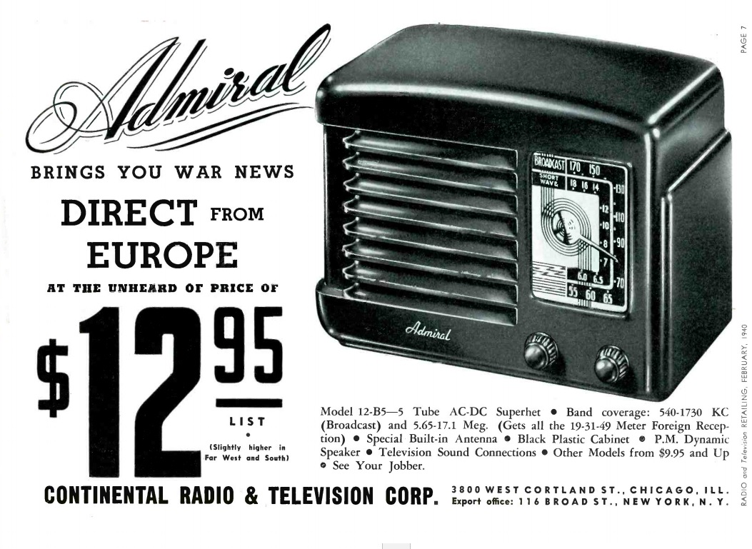
1939DecRadioToday4The set featured six pushbuttons, “feathertouch tuning keys” to be specific. The phonograph was automatic. Unfortunately, it didn’t tune the short waves; it covered only the standard broadcast band. For those wishing to tune in the war news straight from Europe, the Trav-Ler Radio & Television Corp. had just the thing they needed highlighted in the same magazine. Shown at left is the Trav-Ler “War Reporter,” a six-tube set designed specifically to pull in European broadcasts, in addition to the standard broadcast band.


Television Controlled Machine Gun: 1944

1944DecRadioCraftCover

This self-explanatory “television controlled machine gun” appeared on the cover of the December 1944 issue of Radio Craft.  It was not, however, an existing weapon system.  Instead, it was the vision of publisher Hugo Gernsback, who wrote the accompanying article describing the system.

It was intended for a defensive position, and Gernsback admitted that it might eventually be overrun.  But when that happened, he noted, there would be no casualties.  And a second and third layer could then take over.

Gernsback also anticipated active night vision equipment.  He pointed out that his system could be used at night simply by installing some infrared floodlights, which the TV camera would pick up with no difficulty.


1944 Boys’ Life Hallicrafters Ad

1944DecBLIn 1944, with wartime bans in place, Hallicrafters didn’t have any equipment for sale to civilians. But they were gearing up for a postwar boom, and they figured a lot of Boy Scouts would be in the market for radio equipment as soon as the war was over.

This ad appeared 75 years ago this month in the December 1944 issue of Boys’ Life. It encourages young radio fans to send 25 cents to the ARRL to get the most recent edition of “How to Become a Radio Amateur,” a splendid book.


Maurice Goldberg: Minnesota Radio Pioneer

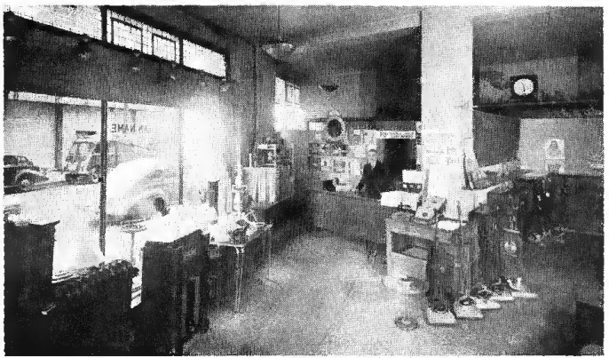
1944DecRadioRetailingShown here in 1944 is Maurice G. Goldberg, the owner of Beacon Radio Service Shop, 142 East Fourth St., St. Paul, MN. The shop had been in business for 20 years, and even before the war had concentrated on service. Indeed, the sign outside read, “if we can’t fix it, throw it away.”

Even with wartime parts shortages, the shop was living up to its reputation of being able to fix anything. And since new sets were not available for sale, his decision to concentrate on service proved profitable.

Goldberg had been able to keep many radios operating by interchanging tubes, with often meant having to rewire the set. He was so flooded with business that backlogs ran about three weeks. He did, however, prioritize oldtime customers. His reasoning was that when conditions returned to normal after the war, many customers would return to local dealers. But the long-term customers would appreciate the loyalty shown to them.

Greenberg also taught at the Dunwoody Institute in the Army training program. He did occasionally get students who were available to help out in the shop, but he did the bulk of the work himself, working long hours.

Goldberg was indeed a Minnesota radio pioneer. He’s listed as of 1924 as the licensee of KFOY, with broadcast 250 watts on 1350 kHz (222.1 meters). This frequency was shared with WAMD Minneapolis, licensed to one Stanley E. Hubbard. The stations were bought in 1928 by the National Battery Company, which merged them together under the new call sign KSTP, with Hubbard as general manager. Power increased to 25,000 watts, and Hubbard re-acquired a controlling interest in 1941.

The photo above appeared 75 years ago this month in the December 1944 issue of Radio Retailing.


Printed Circuits: 1959

Screen Shot 2019-12-04 at 11.45.38 AM
These two television servicemen, pictured on the cover of Radio-Electronics, December 1959, realize that printed circuits are here to stay.  Fortunately for them, as the magazine explains, the boards are becoming very reliable, and are designed to make servicing of television sets easier.