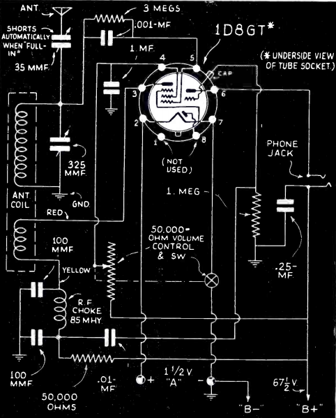
 Field Day 1940 should give some inspiration to those who are operating Field Day 2020.
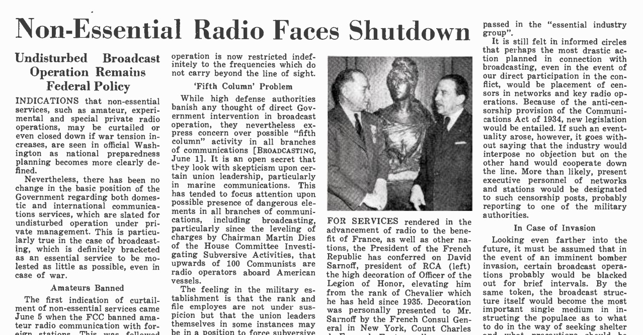
Eighty years ago, the U.S. was still 18 months away from being drawn into the war, but the subject was on the mind of the FCC. Amateur radio operators were not silenced until Pearl Harbor, but there were already restrictions in place, as described in the June 15, 1940, issue of Broadcasting magazine.
The magazine noted that non-essential services, such as amateur, experimental, and special private radio might be curtailed or shut down due to wartime conditions. On June 5, 1940, the FCC banned all amateur communications with hams in foreign countries.
On June 7, the FCC banned portable and mobile operations with a couple of exceptions. First of all, such operations were allowed above 56 MHz, the thinking being that there was little threat from these line-of-sight signals.
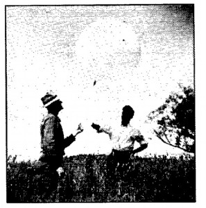
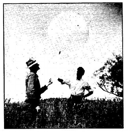
Operators at W8QLU/8 getting ready to launch a balloon-supported antenna, Field Day 1940. Photo, QST for December 1940.
In addition, there was a blanket exception allowed for stations participating in the 1940 ARRL Field Day, which the magazine described as “tests of portable transmitters designed for special use in time of emergency.”
Despite the restrictions, hundreds of ham stations took part in Field Day. One of the high scores was from the St. Paul (MN) Radio Club, W9KYC/9, which made 505 contacts on all bands from 160 to 10 meters. 228 of those contacts were with other Field Day stations, the rest presumably being with home stations.
This year again, Field Day is subject to emergency restrictions, and many of the large multi-transmitter operations will be off the air. Despite initially saying that they weren’t going to do so, the ARRL finally relented and will allow points for contacts between home stations operating with commercial power.
While this rule change is understandable, it would seem odd to stay home and get on the air, while pretending to be in a Field somewhere. While many hams won’t be able to do Field Day this year in the normal fashion, they can operate in an honest-to-goodness Field if they use a bit of creativity.
In 1940, despite a war looming and government restrictions, at least 228 groups of hams were able to lug their bulky transmitters, receivers, and generators to remote locations and get on the air.
One of the purposes of Field Day, then and now, is “tests of portable transmitters designed for special use in time of emergency.” This year, there’s an actual emergency going on. But despite that actual emergency, there’s nothing stopping hams from taking their equipment–which is much smaller and more portable than it was 80 years ago–into an honest-to-goodness Field to put it on the air.
 This year, my wife and I will be operating from a city park near our home. The tentative plan is to be in the two-transmitter class, probably covering 20, 6, and 2 meters. Power will be supplied with the trusty fish-finder battery, and the antenna will be supported by the trusty golf ball retriever. As a trial run this weekend, I set up in our own backyard for the annual Cookie Crumble QRP Contest. Despite poor conditions, I made contacts with Pennsylvania, New Hampshire, New York, and Texas. On Field Day, I’ll repeat the operation. Even though I’m physically distancing myself from others, there’s no reason for me to sequester myself in the basement. I can just as easily operate from a bona fide Field for Field Day.
The ARRL made another temporary rule change this year, and will publish a cumulative score for clubs. I think the idea was that, even with club members operating from their home stations, they can still be part of a club effort. I guess they can pretend they’re all in the same virtual field. And by operating from the comfort of their own home, they can get an even larger score than when they set up multiple transmitters in a real field.
But that rule change applies to all classes of entries–even those who are operating a traditional Field Day from the field. Therefore, I have taken the liberty of forming a new club for the hundreds of hams who figure out a way to operate Field Day as it was meant to be–in the Field.
The new club is named “The Outstanding In Their Field Amateur Radio Field Day Club.” It is open to any and all hams, worldwide, who plan to operate Field Day as a Class A or Class B station, namely, from a remote location with emergency power and temporary antennas. Your setup might be elaborate, or it might be as simple as a $30 Baofeng. If you believe that one contact in such conditions is better than filling up an entire logbook from your air conditioned home station, then this club is for you.
Membership in the Outstanding In Their Field Club is simple. There are no dues or long-term commitment. You can join in one of three ways. If you are gung-ho, then you can sign the club’s articles of association, which you can view at this link. If you’re on board, but not quite to that extent, you can just send me an e-mail to w0is@arrl.net. Or if you’re not sure and want to wait until the last minute, you can join simply by naming the club in your Field Day entry.
Despite war looming, at least 228 hams hit the Field for Field Day 1940. There’s no reason why we can’t do the same. If you also think so, please consider joining The Outstanding In Their Field Amateur Radio Field Day Club.

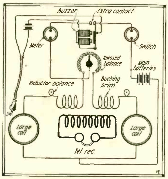
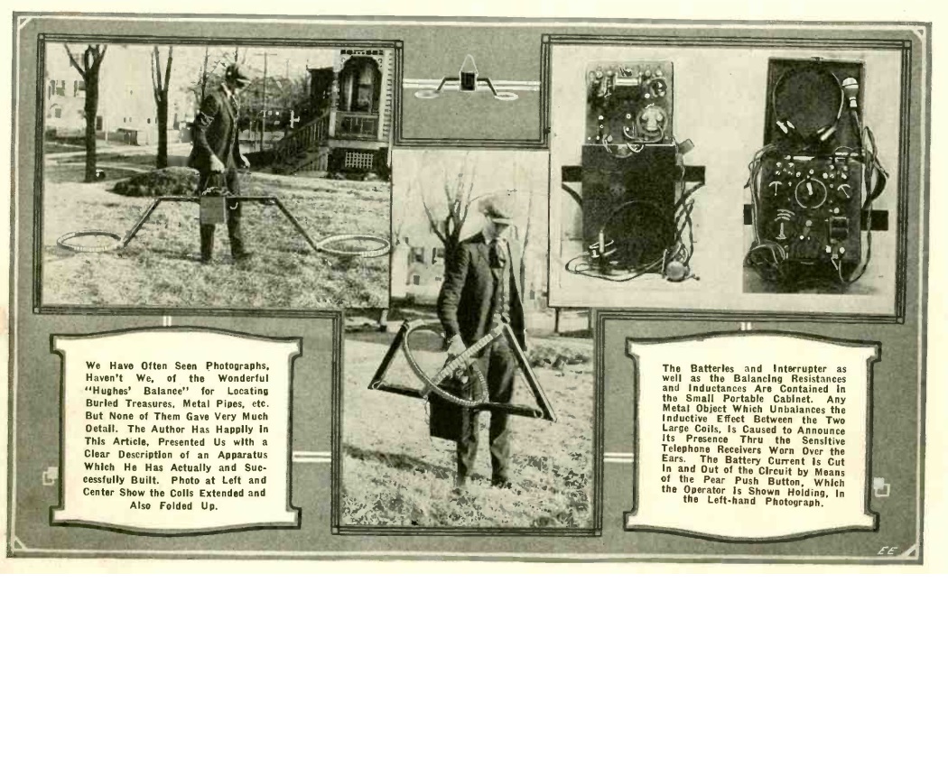 A hundred years ago this month, the June 1920 issue of Electrical Experimenter showed this ingenious metal detector. Like most metal detectors, it relies upon the inductance of a coil increasing in the presence of metal.