Category Archives: Radio history

Science Fair Idea: Eli the Ice Man

1945MarRadioCraftAIf you ask any serious student of electricity to name their favorite ice man, they’ll undoubtedly tell you that it is Eli. Eli the Ice man (a friend of Roy G. Biv) is a mnemonic to help you remember that in an inductive circuit (L), the voltage (E) leads the current (I). And in a capacitive circuit (C), the current (I) leads the voltage (E).

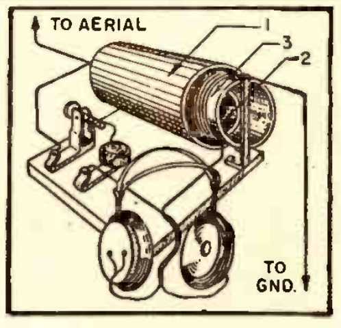
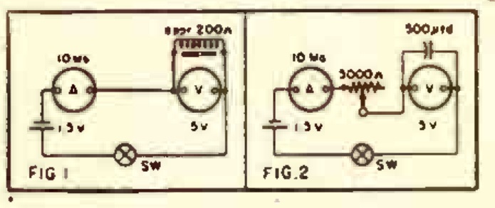
You can prove this concept with this simple experiment shown 75 years ago this month in the March 1945 issue of Radio Craft. In addition to the capacitor and inductor and a few miscellaneous parts, you’ll need a voltmeter and ammeter. During the war, those analog meter movements would have been hard to come by, but these days, you can get buy with two cheap multimeters. Stores sometimes give digital meters away for free, but this experiment will look a lot cooler with an analog meter.

You wire up the circuits and then observe the meter when the current is turned on. In the capacitive circuit, the ammeter will move before the voltmeter. In the inductive circuit, it will be the other way around.


Coil Winding Hints

1935MarPS11935MarPS2According to the March 1935 issue of Popular Science, if you had asked any constructor of a shortwave receiver what the most difficult step was, you would have been told that it was winding the coils. Fortunately, the magazine had some pointers. And since, today, you can’t just walk into the local radio store and buy a set of pre-wound coils, the advice is timely for those who want to build an old-time set.

The first step is obtaining the coil forms. Of course, they’re also unavailable today. But during the depression, there was economic incentive to save a few cents wherever possible, and the magazine showed you how to make your own. You did that by finding an burnt out tube and using its base for the coil. The first step was to remove the glass, and for this, there were two methods. You could soak the tube in water to loosen the cement, and then twist out the bulb. There was also the tried-and-true method of taking a hammer to the glass, as shown in the illustration. The magazine cautioned that covering the tube with cloth first was an important safety precaution.

As for the actual winding, the magazine showed two methods to maintain tension but still have two hands available to wind and guide the wire. You could put a weight on the end of the wire, or use the “walking up” method by putting the end of the wire in a vice, and then walking toward the vice while winding.

1935MarPS3


1945 Crystal Set

1945MarRadioCraftC

Seventy-five years ago this month, the March 1945 issue of Radio Craft showed this crystal set idea, sent in to the magazine by John Haynes of Doe Run, Missouri. The coil, consisting of about 125 turns of wire, was mounted on a coil form slipped over an old shield can, and snugly affixed with gummed paper. A second can slid over the coil, and was adjusted to tune the set.

The magazine noted that a similar idea appeared in the January 1943 issue of the magazine.


1935 Light Beam Communicator

1935MarPM85 years ago this month, the March 1935 issue Popular Mechanics showed how to make this light communicator, said to have a range of about a half mile.

The receiver used a caesium photo cell, which the magazine said could be had for about $3. This was fed into a two-tube amplifier which could drive a speaker or headphone.

For audio amplification at the transmitter end, the system used the household radio receiver, and the magazine explained how to hook up the microphone. The the light beam generator used a system I’ve never seen before. Instead of electrically modulating the light bulb, a mechanical approach was used. The speaker was disconnected and the output was instead connected to a magnetic headphone that had been modified. The outer cap of the headphone was unscrewed and cut so that most of the metal diaphragm was visible. Then, the “diaphragm is slipped off and taken to any plating firm to be finished in the same manner as an audio headlight reflector.” The headphone was reassembled, and the result was a mirror that would vibrate in time with the sound. An auto headlamp was used to illuminate the mirror, and this was focused through a lens with a focal length of about 12 inches.

The result would have been a narrow beam of light that was modulated. At the receiving end, another lens was used to focus the beam on the photo cell.

For a unique science fair project, the advanced student could adapt this project using modern materials.  When I was a kid, I built a similar system using a flashlight as the transmitter.  The bulb was wired in series with the secondary of an audio transformer.  The primary was fed by the output of an amplifier.

For the receiver, I used a solar cell fed directly to the input of an audio amplifier.

1935MarPM2


Testing a Battery with a VOM

1970MarEIFifty years ago, Electronics Illustrated showed this pointer for testing batteries with a multitester. Just measuring the voltage won’t do much good, as the battery will probably show its full voltage, even if depleted, with no load.

The solution is to put a resistor in parallel across the battery. If the battery shows full voltage across this 100 ohm resistor, it’s probably good.

These days, multitesters are even cheaper than they were 50 years ago.  In fact, occasionally stores will give them away free.  If you don’t have one around the house, get one, as you won’t know what you did without it.

Some of the meters below give you an idea of how inexpensive they are these days.

If you don’t have that 100 ohm resistor in your junque box, you can also get it on Amazon.

Some links on this page are affiliate links, meaning that this site gets a small commission if you make a purchase after clicking on the link.


1945 One-Tube Four-Stage Receiver & SW Converter

1945MarRadioCraft3Seventy-five years ago this month, the March 1945 issue of Radio Craft magazine carried this one-tube receiver, submitted to the magazine by Sgt. L.R. Blattner, who was stationed at Tinker Field, Oklahoma. According to the serviceman, the set gave the maximum performance for the number of components, and it’s hard to dispute that claim. Despite having only one tube, the set had a stage of RF amplification, AVC, and two stages of AF.

The signal is first applied to the pentode section of the dual tube, passed through the RF transformer, and then detected by the plate and cathode of the triode. Then, it’s applied again to the pentode, now acting as an AF amplifier. From there, the signal goes back to the triode where it’s amplified again.

The magazine also carried the shortwave converter below, sent in to the magazine by Richard E. Held of Sioux City, Iowa, who reported that he received stations from Tokyo to Brazzaville.  It tuned 7-11 MHz, and used two tubes that the writer had lying around.

1945MarRadioCraft4


School Distance Learning: 1930s

1938Dec3RadioGuide

1937Oct15BCDue to the cornavirus pandemic, schools around the country and around the world are grappling with the issue of how to provide instruction to students by distance learning.  It isn’t a new phenomenon, however, as shown by this article from the October 15, 1937, issue of Broadcasting magazinei

During a Chicago polio epidemic, schools were closed, and the city’s radio stations banded together to broadcast classes for students at home.  The program was so successful that it was to continue even after school was back in session.  Broadcasts would not duplicate material from school, but would supplement it, with a cultural value directed at both adults and children.  The city’s stations would each donate 15 minutes per day of airtime to the programs.

Other schools facing quarantine were looking to Chicago’s successful venture as inspiration for their own.  The Chicago schools had been contacted by educators and broadcasters in the U.S. and Canada for pointers.

The photo above is another example from 1938.  This one isn’t because of an epidemic, but because of a fiscal emergency in Dayton, Ohio, as recounted in an earlier post.


1945 MacGyver Power Supply

1945MarRadioCraftB

According to Wikipedia, MacGyver was born in either 1951 or 1952, so he couldn’t have been responsible for this wartime power supply. Instead, it was sent in to the the March 1945 issue of Radio Craft by one Richard F. Reed of Jacksonville, Florida. But MacGyver must have been inspired by Reed, since this power supply ingeniously makes use of available parts, despite wartime shortages.

Reed needed to 90 volt power supply, and used this circuit to get it out of a 1.5 volt battery. The transformer could have been an audio output transformer, but Reed had on hand a model plane induction coil, so he used that. In lieu of an inverter, he used a 1.5 volt buzzer in series with the transformer.

For a rectifier, he used the starter from a fluorescent light. He reported that the supply put out 95 volts at 25 mA.


1945 Three Tube Broadcast Set

1945MarRadioCraftThis handsome but utilitarian wartime cigar-box set was put together by G.L. Keirstad of Toronto, and described in the March 1945 issue of Radio Craft magazine. According to the author, the set pulled in all four of the local Toronto stations, as well as WGR and WBEN in Buffalo. At night, it would also get the New York stations with loudspeaker volume quite adequate for a personal radio.

1945MarRadioCraft2


Stromberg-Carlson 1945

1945Mar12LifeIn March 1945, the war was still on, and that meant that there was no production of civilian radio receivers. But the manufacturers knew that there would be a big sales boom as soon as the war was won, and they were getting their name before the public.

This ad from Stromberg-Carlson appeared in Life Magazine 75 years ago today, March 12, 1945.  And the company was betting on the miracle of FM being the wave of the future.  These young people are listening to some postwar program daydreaming.  The girl dreams of marrying the man of her dreams, and her tenderfoot little brother dreams of being the patrol leader of the best patrol in town.