Category Archives: Radio history

1940 Admiral Radios

1940AprRadioRetailing
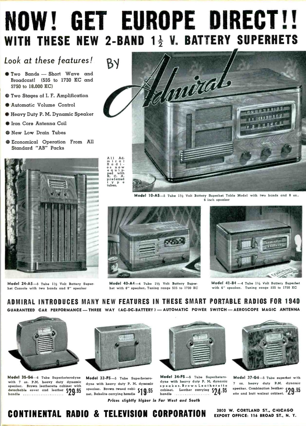
Eighty years ago, this ad showing some of the Admiral line of radios appeared in the April 1940 issue of Radio Retailing. Even rural Americans without household electricity would be able to pull in Europe direct with these battery shortwave sets. The sets all featured 1.5 volt filament tubes, and the combination A-B battery packs were readily available.

The model 10-A5 was a table set that tuned the standard broadcast band (including police calls, since it went as high as 1730 kHz) and 5.75-18 MHz shortwave to hear the war news directly from the capitals of Europe. The model 24-A5 was a comprable console model.

For broadcast only, the model 40-A4 and 41-B4 table sets were shown. The ad also featured four portable sets that could operate from AC, DC, or internal battery. The ad promised guaranteed car performance.


1920 Induction Coil & Quenched Gap

1920AprilPSA hundred years ago this month, the April 1920 issue of Popular Science carried this ad for an induction coil and spark gap said to have a range of 25 miles using direct current. The induction coil, which consisted of a vibrator, primary winding, and secondary winding, would produce a high voltage alternating current using a 6 volt storage battery. This was fed to the quenched gap, which produced the spark to be radiated by the antenna. Together, the two components were the heart of the transmitter. The induction coil was also available in a 32 volt version for use on farm lighting circuits of that voltage. This setup was promised to make other amateurs in your state sit up and take notice when your signal showed up in the ether.

The two components were available together for $33.50. It was recommended to buy the set from your local dealer, but if none was available, the American Radio and Research Corporation would send it for five dollars down, with the balance plus postage paid C.O.D.

Since the set used high-quality surplus Signal Corps parts, only a limited number of sets could be made.

The ad showed the company has having its factory at Medford Hillside, Mass., with offices at 29 Park Row, New York.


Reminiscences of CKY Winnipeg

1945AprManCallineSeventy-five years ago, station CKY in Winnipeg asked its listeners to submit reminiscences of the early days of radio. Many of these were published the the station’s monthly program guide, Manitoba Calling. This one appeared in the April, 1945, issue, which also carried the photo above of the station’s studio in 1928:

This one was sent in by W.J. Cooper of Steep Rock, Manitoba. The magazine noted that his was a familiar name as a loyal listener in the early days of the station.

My experiments in radio go back to the days when it was called wireless telegraphy. I think it was in about 1916 that I got some spark coils and rigged up a spark set. For a detector
I used two carbon blocks filed to a sharp edge. They stood on end and a fine needle was laid across the sharp edges. Our two stations were only a couple of hundred yards apart, but the
junk actually worked.

My next experience came in about 1922 -1923. Radio stations were springing up all over the continent. There were several stations operating in Winnipeg. (2 in 1923). They quit when
CKY took over broadcasting in Manitoba in 1923. My first set was almost entirely home -made, with the exception of the tube, socket, phones, and batteries. It took up all the space in a cabinet almost as big as a suitcase. The hook-up was a spider-web 3 circuit, single tube. After many nights’ efforts it was made to work. The first reception heard over it was the voice
of the announcer (now editor of Manitoba Calling). He closed by saying “goodbye everybody” and by blowing the call letters CKY on a whistle….

One of the big drawbacks of the early radio sets was that there were too many controls for anyone but the builder to know how to operate. One of the well known super-heterodyne sets had about 50 knobs, dials, verniers, jacks, switches and a couple of meters . . . Hardly anyone but the demonstrators could operate them. However, with the coming of sets with fewer controls, business soon picked up…. CKY was responsible for many pioneer achievements in Canadian broadcasting. Programmes were picked up by a listener’s receiving set in Winnipeg. (Actually two sets, one in Fort Rouge and one on Atlantic Ave., operated by Manitoba Telephone System officials). One night they broadcast the Night Hawks programme from WDAF in Kansas City.


Blondie, 1940

1940April13RadioGuideIn radio, the show must go on. And that’s so even if the leading lady is in the hospital. Shown here is Penny Singleton, playing the role of Mrs. Bumstead in the Blondie radio series. She was involved in an auto accident that resulted in two broken ribs. But from her hospital bed, she’s reading her lines.

The photo appeared 80 year ago today in the April 13, 1940, issue of Radio Guide.


Death of FDR: 1945

On this day 75 years ago, April 12, 1945, President Franklin Delano Roosevelt died, and President Harry S Truman was sworn in.

You can hear some of the radio coverage at this video:

https://www.youtube.com/watch?v=djcuHhg6PRQ


Lafayette Sunflex KT-132

1960AprEI1960AprEI2Sixty years ago this month, the April 1960 issue of Electronics Illustrated carried a review of the Lafayette Sunflex radio kit (model KT-132). It derived its name from the fact that the two transistors did the work of three, thanks to reflexing, and that the set could be powered by the sun, using an optional solar battery. The set was said to be very sensitive, and also ran off two penlite batteries. Power switching was done by plugging the earphone into the appropriate jack–one for the internal battery, and the other for the solar battery.

The kit retailed for $11.95, with the solar battery selling for $7.75.  According to the magazine, the kit took about six hours to put together.


Build a Theremin!

1955AprPE
1955AprPE2This musician-electronic hobbyist, shown on the cover of the April 1955 issue of Popular Electronics is playing the Theremin that he built according to the magazine’s plans. The magazine stressed that the project was not for beginners, but for those with some electronic experience, it was fairly easy to assemble.

Once built, the owner could use the instrument to play music, or to provide background sound effects for amateur theatricals. “A complete show can be produced by combining its abilities to emit both music and sound effects.”

The instrument depended on hand capacitance on the two antennas. The one marked “T” was the tone. The variable capacitance changed the frequency of an RF signal generated by an oscillator. This was mixed with another oscillator to produce a heterodyne which was amplified. The “V” antenna controlled the volume.

Several column inches were devoted to instructions on how to play the instrument, the final one being: “Practice! Practice! Practice! Practice!”  To give an idea of what the instrument sounds like for someone who did practice, here’s what a 1929 Theremin sounds like:

Building the Theremin today with modern solid-state components would probably be simpler, and definitely much cheaper than 65 years ago.  You can buy a Theremin already assembled.  If you just want to experiment with the concept, you can start with this inexpensive kit.


Answer to Yesterday’s Quiz

1970AprSciElecYesterday, we showed this diagram from the April-May 1970 issue of Science & Electronics magazine and asked what current is shown on the ammeter.

The puzzle is easier than it appears, once you see the trick.  The answer is 3 amps.  Despite the confusing diagram, the three resistors are wired in parallel, so the total resistance is 1 ohm.  You can do the math in your head using the “reciprocal of the reciprocals” method.  1/3 + 1/3 + 1/3 = 1, and 1/1 = 1.  To get the current, it’s 3 volts divided by 1 ohm, which equals 3 amps.


Today’s Quiz

1970AprSciElecToday’s quiz appeared 50 years ago this month in the April-May 1970 issue of Science & Electronics magazine. What is the current shown on the ammeter?

This was sent in to the magazine by a reader who was given the question during a job interview for a position as an electronic technician. We’re guessing he didn’t get the job, since he wrote to the magazine to explain it. If you’re also stumped, we’ll have the answer tomorrow.


Larsen E. Enterprises, 1960

LarsenEI’ve never had the opportunity to visit yet, but my bucket list certainly includes a trip to the headquarters of Larsen E. Industries. The company was founded by technical genius Larsen E. Rapp, WIOU, sixty years ago this month. This announcement of the momentous event appeared in the April 1960 issue of QST.

From most browsers, clicking twice on the image will show you an enlarged version.