Category Archives: Radio history

1920 One Tube Regenerative Receiver

1920MayPS2This simple regenerative receiver circuit appeared in Popular Science a hundred years ago this month, May 1920. It was sent in to the magazine by one Edward T. Jones, who reported that it used a resonant antenna, connected by what he called a “balancing circuit.” He reported that this circuit drew signals from the antenna in a much greater proportion than static.

He reported that connecting the optional variable capacitor resulted in greater signal strength, but with some loss of selectivity.


1940 Portable Hand-Crank Radio-Phono

1940MayPMxFrom 80 years ago, here’s another example of a hand-crank phonograph, but with electrical rather than mechanical sound reproduction. The set in question is a portable radio-phonograph combination.

The radio was a four-tube superhet, powered by batteries. It made perfect sense to use the hand-crank motor, since the motor would unnecessarily run down the batteries.

The set, which appears to be from General Electric, was shown in the May 1940 issue of Popular Mechanics.


1940 Six Tube Superhet

1940MayPM4Eighty years ago this month, the May 1940 issue of Popular Mechanics showed how to put together this project for advanced radio hobbyists. It was a three-band six-tube superheterodyne receiver capable of tuning 530 kHz to 18 MHz. It was an update to a four-tube set shown in the December 1939 issue, as that project had left space on the chassis for the upgrade, and most of the parts from the original set were re-used.

Unfortunately, I don’t see any indication that the set had a BFO, so while it was probably a good receiver for voice signals, it couldn’t be used for code.

1940MayPM3


1940 One Tube “Baseball Special” Portable

1940MayRadioCraftEighty years ago this month, the May 1940 issue of Radio Craft carried the plans for this simple one-tube broadcast set dubbed the “Baseball Special.” The author put the circuit together to be able to listen to the play-by-play while sitting in the stands. He noted that the set was never meant to be a DXer, but it pulled in the local stations, the ones that broadcast the game.

The circuit used a 1D8GT triple diode-triode-pentode tube. The diode section was not used, the pentode was used as a regenerative detector, and the triode served as audio amplifier. A short piece of wire served as the antenna. A camera case was used to house the radio, although the author noted that the works could just as easily be tossed into a paper bag.


1945 One-Tube Space Charge Receiver

1945MayRadioCraftThis wartime circuit from the May 1945 issue of Radio Craft is about as simple as it gets. It was sent in to the magazine by Jim Brophy of Chicago, who reported that it gave good volume on all of the local stations.

What’s somewhat remarkable–in addition to the low part count–is the fact that the set used two flashlight batteries for the filaments, and only three penlight cells for the “B” battery. The low voltage requirement was due to the space-charge principle. The grid closest to the cathode in the tetrode tube (in this case, a type 49) was kept at a positive voltage. The magazine’s editors noted that this was one of the oldest effects in tetrode tubes, but had dropped into obscurity. But with wartime shortages of B batteries, the magazine noted that it was worth some experimentation.

The name of the person who submitted the idea, Brophy, rang a bell.  It doesn’t sound like a very common name, but also in 1945, one Loretta Brophy was working at WABD-TV in New York.


1945 Ecophone Model EC-1 Receiver

1945MayRadioCraft2Yesterday, we showed a Hallicrafters “morale” receiver from 1945, and today, we see this ad for another one, from the May 1945 issue of Radio News.  This femme fatale has taken an interest in this soldier, and it’s not out of the question that she’s a spy.  Fortunately, she won’t get anything out of him, because all he does is sing the praises of the Ecophone Model EC-1 morale receiver.

He’ll tell her that the set is a compact communications receiver with every necessary feature for good reception, and that it tuned from 550 kHz to 30 MHz in 3 bands.  He’ll let slip that it has an electrical bandspread, six tubes, a built-in speaker, and that it runs off 115-125 volts AC or DC.  But since none of that was classified, the Army had nothing to fear.


Hallicrafters RE-1 Sky Courier

1945MayRadioNewsShown here is the Hallicrafters Model RE-1 Sky Courier receiver from 1945. For the G.I. far from home, the radio was as important as mail call in staying connected with home. Early in the war, whatever receiver could be found was pressed into service, but the harsh conditions meant that the military needed a rugged “morale” set, and the RE-1 was the answer.

The set could operate from batteries (90 and 9 volts) or AC power. The method for switching was ingenious. To switch to battery operation, the line cord was inserted into a jack in the back of the radio. The prongs of the cord completed two circuits, and thus served as a DPDT switch, connecting the batteries. The set tuned 550-1600 kHz and 2.8-19 MHz, and contained a built-in antenna.

Above all the set was rugged, and was designed to resist both corrosion and fungus.

The picture and description appeared in the May 1945 issue of Radio News.


1920 One Tube Transmitter-Receiver

1920MayElecExp3Pierre H. Boucheron was obviously our kind of people, as evidenced by his article a hundred years ago this month in the May 1920 issue of Electrical Experimenter, entitled “A One Tube Radio-Telegraph and Radio-Phone Transmitter.” It appears that Boucheron was on the cutting edge of radio technology. He starts his article by noting: “Amateurs, do you realize that a great deal of interesting experimenting is at the present day done by many amateurs all over the country employing undampt (in other words, CW, rather than spark) transmission? For the most part this is being accomplisht by the use of one or more vacuum tubes on oscillating circuits well below two hundred meters (in other words, above 1500 kHz). This is possibly one of the reasons why you do not hear them. Another reason is that it is continuous wave and not readily intercepted when ordinary dampt wave receivers are employed.”

He went on to point out that there were hotbeds of such activity in places such as New York, Philadelphia, Boston, Baltimore, Chicago, New Orleans, San Francisco, and Los Angeles. He pointed out that ranges of five miles were easy on 100 meters (3 MHz), and offered a number of circuits to get on the air.

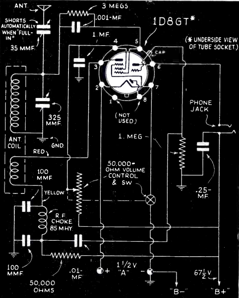
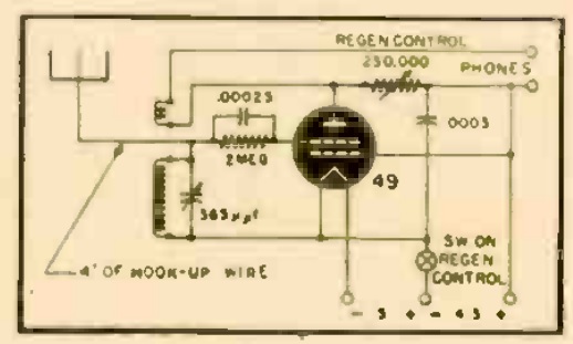
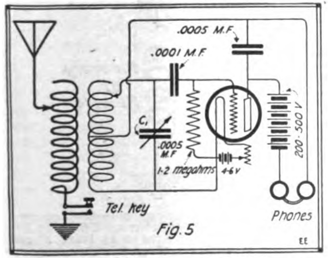
One of the most intriguing is shown above. It’s a single tube regenerative receiver, suitable for pulling in CW signals. But since it can quickly be adjusted to oscillate, a key between the antenna coil and ground would turn it into a transmitter.

1920MayElecExp4
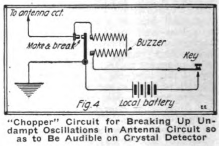
Another interesting idea is the one shown at the left. If you own an audion, but your buddy across town doesn’t, it’s possible to turn your undamped CW signals into faux spark signals. A buzzer is simply placed in series with the antenna circuit of your transmitter. When it’s keyed, the antenna is interrupted many times per second. The result is a signal modulated at the frequency of the buzzer, which can be picked up by your buddy with a crystal detector.
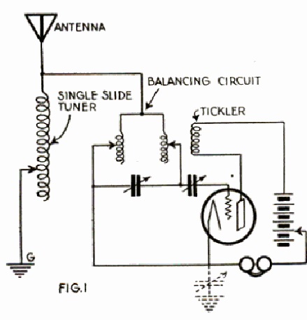


1940 Code Practice Oscillator

1940MayPMThese young men are mastering the code, thanks to this inexpensive oscillator featured in the May 1940 issue of Popular Mechanics. The set featured a single 117L7-GT tube and ran straight off the line current. The switch provided a choice of four tones, and there was plenty of volume through either the speaker or headphones.

1940MayPM2


Radio Mercur, 1960

1960MayEIIf you look carefully at this picture, from the May 1960 issue of Electronics Illustrated, you’ll see at the top of the mast a Yagi antenna for 89.55 MHz. The ship is the Cheeta, and flies the Panamanian flag.

The ship is in international waters off the Danish coast, and is serving as the transmitter site for Radio Mercur, a pirate radio station. From studios in Copenhagen, programs were recorded in Danish, Swedish, and English, and brought to the ship anchored in international waters.

According to the magazine, the sale of FM receivers boomed in the ship’s listening area of about 50 miles, with an ERP of about 1500 watts. The Danish government had been unable to silence the station, but this changed a few years later with legislation forbidding anyone in Denmark from cooperating with the broadcasts.