Author Archives: clem.law@usa.net

Incentive Licensing: 1969

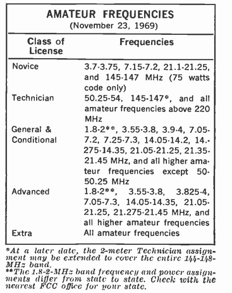
1969NovPESince the early 1950’s, most U.S. amateur radio operators shared the same privileges. With the exception of novice and technician licensees, all hams (general, advanced, and extra class) could operate on the same frequencies.

The Soviet Sputnik served as a wake-up call for U.S. science, and one result was that there was a call for better training of hams. It was reasoned that they should learn how to pass the tougher tests, and that they needed an incentive to do so.

Thus, “incentive licensing” was born. Even though it’s been over a half century and most of the supposed bad guys (as well as most of the “victims”) are dead, there’s still resentment in some quarters. This is because many hams lost privileges with incentive licensing, and they had to pass more tests to get those privileges back.

The first phase of incentive licensing took place in November 1968. The new rules had been announced some time in advance, and many hams had used the time to upgrade to advanced or extra. For those who hadn’t, some privileges were taken away in 1968. And 50 years ago today, November 23, 1969, the second phase took effect. As of that date, the privileges were as shown in the chart above, which was taken from the November, 1969, issue of Popular Electronics.

Similar privileges were in effect when I got my license a few years later, although there had been some changes. First of all, the exclusive extra CW segment when I got licensed was the bottom 25 kHz of 80, 40, 20, and 15, as opposed to the 50 kHz shown here. Also, the novice privileges had changed slightly. When I got my license, novices no longer had 2 meter privileges. (A few years before, novices had been allowed ‘phone on 2 meters, but by 1969, it was CW only.) The 15 meter novice band got a little smaller, as the top 50 kHz were shaved off.  By 1974, novices were also allowed on 28,1 to 28.2 MHz CW.  Finally, the 40 meter novice band was shifted down to 7.1 – 7.15 MHz by the time I was licensed.

RCA Toy Phonograph: 1939

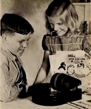
RadioTodayNov1939Maybe it’s just me, but the girl looks like she has some kind of sinister plan in mind. Ostensibly, Santa just brought this RCA toy phonograph which, according to the caption, should have been on every parent’s list, since it sold for only $4.95. But if I were little brother, I would be careful.

The picture appeared 80 years ago this month in the November 1939 issue of Radio Today.


They Don’t Make ‘Em Like They Used To

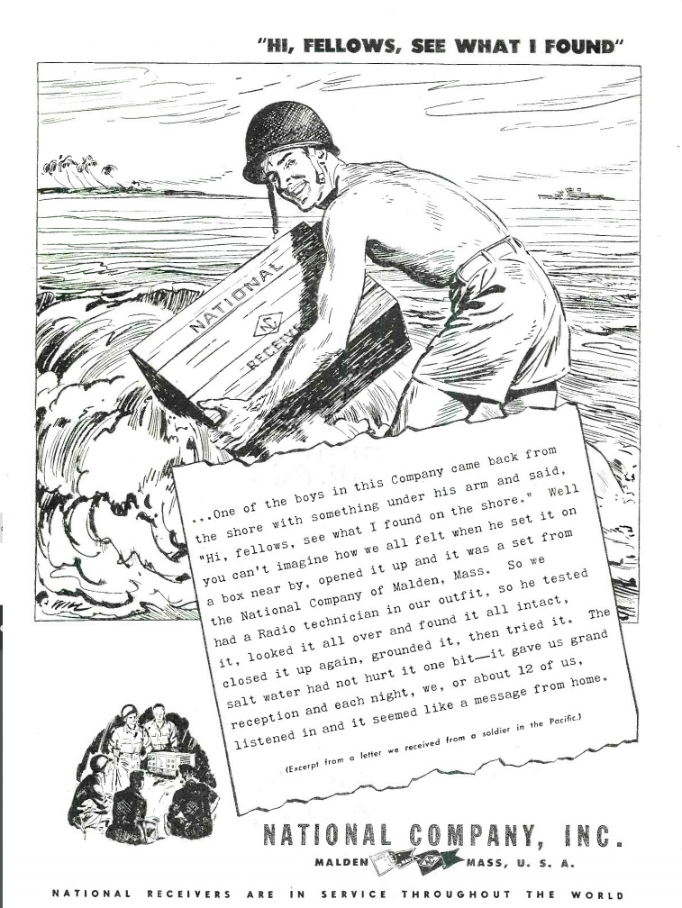
1944NovRadioNews2This compelling testimonial appeared in Radio News 75 years ago this month. Somewhere in the Pacific, a soldier found a crate washed up on shore, with a National receiver inside. He and his buddies checked it out, cleaned it up, grounded it (probably a good idea), and fired it up. Despite its time spent in the brine, it functioned flawlessly.


1919 Aeronautical – Radio Wedding

1919NovElecExp2We’ve previously reported two aeronautical weddings via radio, in April 1922 and June 1922.
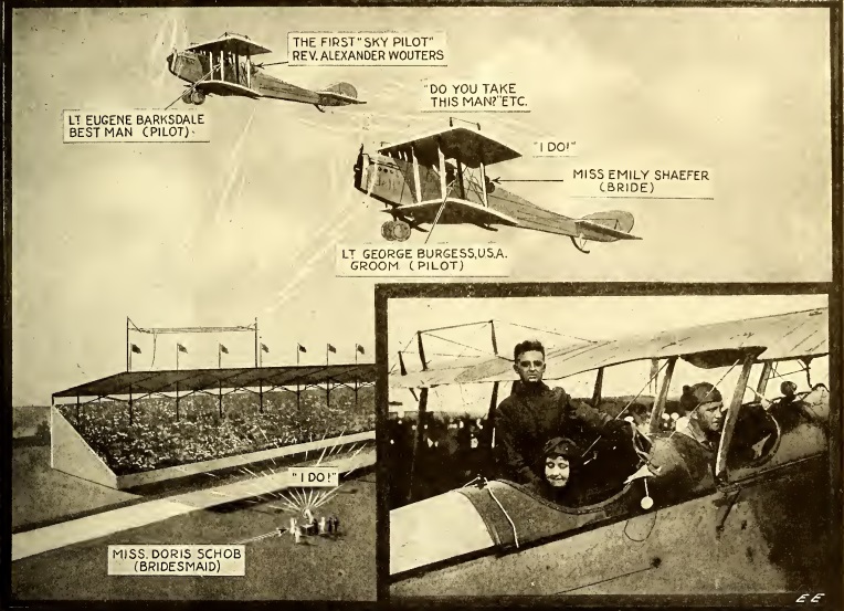
Those, however, were not the first, since the wedding of Lt. George Burgess and Emily K. Schaefer took place in 1919. The bride and groom were in one plane, piloted by the groom. The minister, Rev. Dr. Alexander Wouters was in another plane piloted by best man Lt. Eugene Barksdale. The event took place at the Police Field Day festivities at the Sheepshead Bay Speedway near New York City.

A receiver hooked to a large public address system was in place on the ground, allowing the gathered guests to hear the entire ceremony. At 5:10 PM, the planes took off from the speedway. As those on the ground listened, the minister began to read the ceremony, and the couple exchanged vows. A few minutes later, one of the planes announced “we are coming down,” and the bride and groom landed to applause and waving hats. As the couple moved to an automobile, the bridal party rode past the stands while the police band played the wedding march.

Sadly, Lt. Burgess died in a firy plane crash in 1925 at New Salem, PA. After an airshow in Washington, he was flying to Dayton Ohio with an editor and photographer from the Dayton Herald. In a thunderstorm, the plane crashed to the ground, killing all aboard. His obituary described him as a wireless expert and instructor in radio airplane communications.  He is buried at Arlington National Cemetery. The couple had two children. The bride died in 1969 at the age of 77.

The best man also died in an airplane crash in 1926.  Barksdale Air Force Base in Louisiana is named in his memory.


The Möbius Resistor

1969NovEI

Mobius resistor. Wikiepdia image.

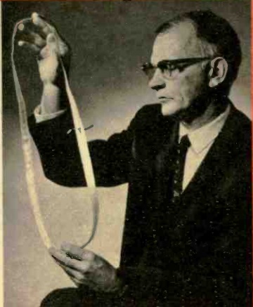
Shown here in the November 1969 issue of Electronics Illustrated is Richard L. Davis of Sandia Laboratories, the inventor of the Möbius resistor, US Patent 3267406A.

Many youngsters will be familiar with the Möbius strip. It’s a three-dimensional object with one side and one edge. It is formed by taking a strip of, for example, paper, making a twist, and then taping the ends together. To prove that it has one side, the young scientist can draw a line down the middle. Eventually, the line will connect up, but only after covering “both” sides of the strip, in effect proving that there is only one side. The strip can also be cut along that line, which will form another strip, this one non-Möbius.

Davis used the Möbius strip to form a resistor. His strip of paper was coated with foil. When it was attached together. The outside of the strip formed a continuous conductor, and connections were made directly opposite. The result was that current was flowing on the outside of the strip, but in opposite directions. Therefore, the magnetic fields cancelled out, making the resulting device non-inductive. This proved useful at UHF, since the stray reactance of a resistor would otherwise be very significant at those high frequencies.

Students looking for an interesting science fair project could make either a Möbius strip or a Möbius resistor.  A student will almost certainly get a participation ribbon by making the strip and then unsuccessfully attempting to cut it in half.  But more advanced students, armed with an inexpensive RCL meter, can get the blue ribbon by showing that the inductance disappears by adding the twist to the strip.


The Battery is Dead!

1949NovRCAServiceNews

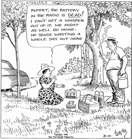
You can say one thing for this woman: She had her priorities in the right place. The battery in the radio was dead, so there was nothing to do but go home. The cartoon appeared in the November-December 1949 issue of RCA Service News. It was reprinted from the New York Herald Tribune, apparently the August 10, 1949 edition.

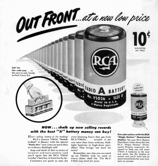
Of course, if her dealer had heeded the advice on the next page and sold her genuine RCA batteries, this probably wouldn’t have happened.

1949NovRCAServiceNews2


Homemade Radio Telescope: 1959

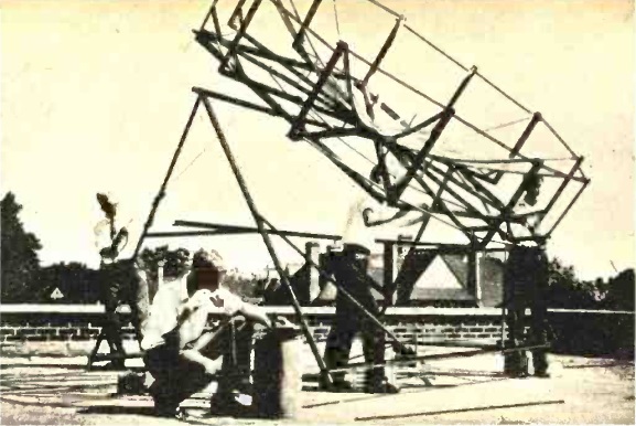
1959NovEI2The English high school students shown here in the November 1959 issue of Electronics Illustrated put together this Radio Telescope, at a total cost of about $40. Led by sixteen year old Doug Miller, the students at the Dartford Grammar School near London had already pulled in signals from the Milky Way, the sun, and the constellation Sagittarius. Parts for the receiver came from donated a donated TV set.


1919 Forest Service Heliograph

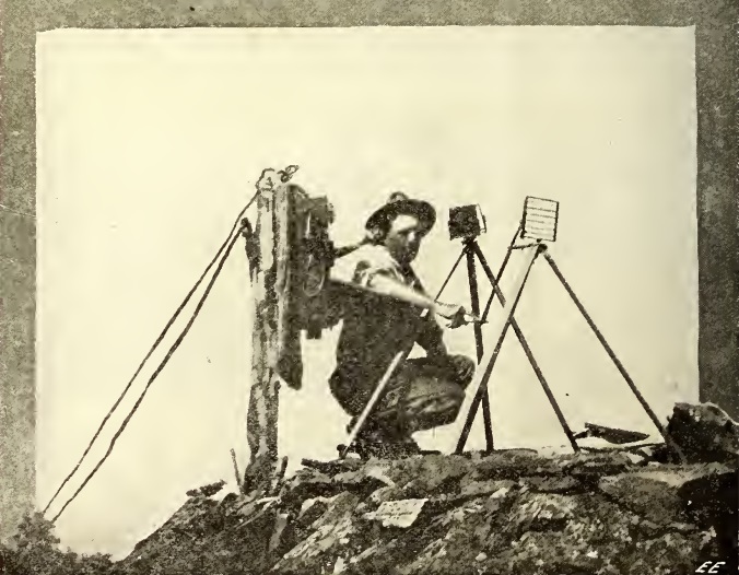
1919NovElecExpOne hundred years ago, the forest ranger shown here is acting as “lookout man” atop some Western peak. As he watches for forest fires, he has at his disposal detailed maps of the area, as well as two means of communication. When he spots a fire, he can call in the bearing to headquarters on the telephone. To communicate with other spotters in areas too remote for a phone, he has the heliograph. On clear sunny days, the device had a range of up to 45 miles.

The first Forest Service heliograph units had originated with the Army Signal Corps, but more compact units suited to forest fire fighting were procured. Seven rangers were initially trained. Even though they had no prior knowledge, they became proficient operators in a very short time.

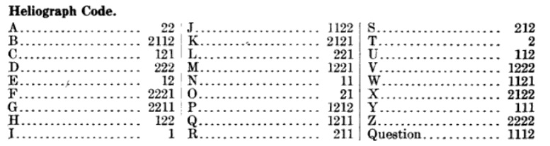
While Morse Code could be used, it was found that the Myer Code, shown below, was more reliable for visual signaling. The letter P, for example, is 1211. The one indicates a long flash, and the 2 indicates two short flashes.

MyerCode

The top photo appeared in the November 1919 issue of Electrical Experimenter. More details of the system can be found in a 1914 Forest Service Publication, Systematic Fire Protection in the California Forests.  The heliograph instrument consisted of a mirror, which was oriented so that it reflected the sun on the receiving station. A shutter in front of the mirror was used to key the beam on and off. To call another station, the sending station would send a quick succession of flashes until acknowledged. Then, each station would turn on a steady flash to make adjustments. When the mirrors were in place, the sending station would proceed with its message. The average speed of transmission was found to be about four words per minute.

Plans for a simple heliograph can be found at an earlier post.


1944 Three Tube Regen

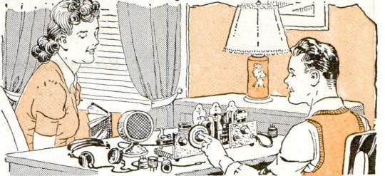
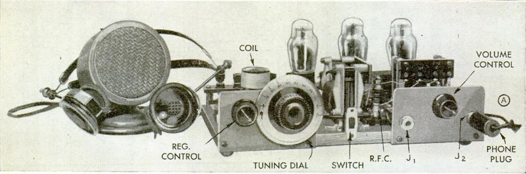
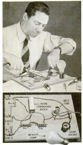
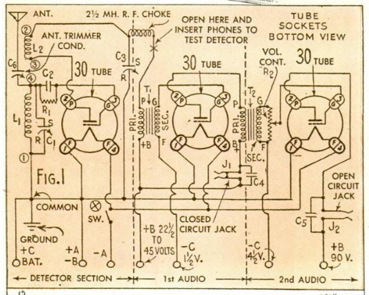
1944NovPM3The young man shown here is pulling in the short waves thanks to a simple receiver designed around wartime parts shortages. The set used three tubes, which could be types 30, 199, or 201-A, obsolete tubes used by older battery sets. It featured two stages of audio amplification, and could drive either headphones or a small speaker. It pulled in shortwave signals from 160 to 10 meters with homemade plug-in coils. The detector was regenerative, with a variable capacitor controlling regeneration.

1944NovPM4

1944NovPM6If B batteries were unavailable (a likely scenario given wartime shortages), then the transformerless battery eliminator shown here could be used.  The set appeared in Popular Mechanics 75 years ago this month, November 1944.

1944NovPM5


1939 Mobile Rig

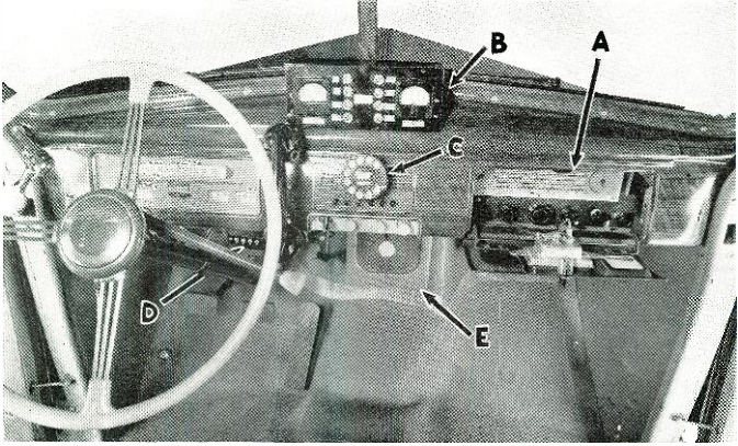
Screen Shot 2019-11-14 at 11.50.46 AMShown here in the November 1939 issue of Radio News is a mobile installation dubbed the “Diplomatic,” which could be used by hams, or also for other mobile applications such as police radio. It is shown here in a 1939 Pontiac, but the same equipment is also shown mounted in a Chevy. The receiver, a Howard 438, is tucked away in the glove compartment, and most of the transmitter is located in the trunk. The dial on the dash is hooked to a stepper relay in the trunk, and is used to turn on the filaments and turn the bandswitch.