Radio Scouting in 1940

Radio and scouting have a long association, as shown by these two photos from 75 years ago this month, in the October 1940 issue of Boys’ Life1940OctBLThe first shows scout Edwin Parkerson of Troop 50, Houston, Texas, listening to music in this set he built to bring to camp.  A scout is kind, and Parkerson undoubtedly let his friends take a turn listening shortly after this picture was taken.

Assuming he did share the headphones, it was probably good for a bit of karma.  Sixteen years later, one Edwin Parkerson of Houston renewed his hospitalization insurance policy, but due, no doubt, to some little mix-up, the premium check bounced.  The insurance company apparently put the check through a second time without incident.  But during the intervening time, Mr. Parkerson’s wife was taken to the hospital, and the insurance company claimed that the policy wasn’t in effect and denied coverage.  The Texas Court of Civil Appeals ruled that the policy was in effect.  Parkerson v. American Hospital Life Ins. Co., 322 S.W.2d 26 (Tex. Civ. App. 1959).

While scout Parkerson was listening to the radio through headphones, the scouts in Nashville were probably getting ready to build a loudspeaker set, since they’re shown here getting some pointers from the staff of WSM.  The caption reports that nearly a hundred Nashville scouts had formed a radio patrol, and were getting technical lessons from the station’s technical staff.

1940OctBL2

Click Here For Today’s Ripley’s Believe It Or Not Cartoon


SD’s Betsy Ross and KGFX, Pierre

KGFX194074 years ago, Life Magazine, October 6, 1941, carried this image of Ida McNeil, the owner and operator of KGFX, Pierre, South Dakota.

If the studio looks a bit cramped, that’s because it is located in her home at 510 Summit Avenue, Pierre, SD.  Both the transmitter and studio remained at that location until 1958, when the transmitter was moved to Ft. Pierre.  The studio remained at the McNeil home until 1964.

The station’s roots date back to 1912 when Ida’s husband, Dana McNeil, was first licensed as 9ZP.  In 1916, he was licensed as 9CLS.  According to the FCC’s card file for the station, the broadcast license for KGFX was first issued on August 15, 1927, with the licensee listed as Dana McNeil,  The station was originally at 1180 kHz, moving to 580 kHz in 1928. In 1932, it moved to 630 kHz, where it remained until 1967.

The 1932 move from 580 appears to be prompted by WNAX, 180 miles away in Yankton, which applied on March 9, 1932, to increase its power on 570 kHz. The WNAX application is referenced in KGFX’s FCC record. WNAX has one of the largest coverage areas of any AM station in the country, and moving KGFX away from the adjacent channel was probably necessary to make that possible.

In 1967, the station made its final move on the dial to its present day 1060 kHz, with 10 kilowatts daytime and a pre-sunrise authority of 500 watts. In 1974, the station was granted authority to run 1000 watts at night.

Mr. McNeil died in 1936, and the FCC record shows the license transferred to Ida McNeil, as the administratrix of his estate, effective March 26, 1937. The license remained in her name until 1962, when it was transferred to Black Hills Radio, Inc.  In 1940, when this photo was taken, the FCC record shows that the station was licensed with 200 watts on 630 kHz between 9:30 AM and local sunset.

Even though the station was licensed commercially, the McNeils operated it as a public service, believing that radio stations should serve the community. The station began accepting commercial advertising in 1932, but the majority of the air time was still devoted to public service. One of the station’s most popular programs was “Hospital News,” in which she broadcast announcements regarding the condition of patients at Pierre’s St. Mary’s Hospital. The physicians at the hospital were initially dismayed by the idea of public announcements about their patients, which they viewed as unethical. But because of difficulties with transportation and communication in rural South Dakota, they soon realized that the program provided a valuable public service, and gave their cooperation.

South Dakota flag, 1909-1963.

South Dakota flag, 1909-1963.

Being a broadcaster was not Mrs. McNeil’s only claim to fame.  Life magazine identified her as the Betsy Ross of South Dakota, since she had designed the state’s flag in 1909, her design remaining in use until 1963.

Mrs. McNeil was born Ida Anding in 1888 in Winona, Minnesota. Her father was a steamboat engineer, and the family moved to Pierre in 1896 when he came to supervise the overhaul of a ferry. She graduated from high school in 1906 and went to work for the South Dakota Department of History, where she was employed when she designed the state flag.

She married Dana McNeil, a railroad conductor, in 1921. While he was on runs between Rapid City and Pierre, she began broadcasting to him over his amateur station. After she realized that he was not the only listener, she began developing a regular programming format, and they obtained the commercial license for KGFX in 1927. In addition to running the radio station, she served as the weather bureau’s official observer between 1935 and 1942.  She died in 1974 at the age of 86, having retired from the radio business with the sale of the radio station twelve years earlier.

Click Here For Today’s Ripley’s Believe It Or Not Cartoon



Hytron Tube Test Station, 1944

Hytron1945The wartime Hytron Corporation worker shown here is using a tube tester, but it’s probably a bit bigger than the one down at the drug store. She is operating a master test station for measuring various attributes of transmitting vacuum tubes. It was described in the October 1944 issue of Radio News.

A year later, the editors were undoubtedly looking for a stunning picture for the cover, so they went ahead and used it 75 years ago this month, in the October 1945 issue.

The test station had various power supplies, as well as precise measuring instruments for voltages and currents to each tube element. The nicely crafted drawers provided storage space for jumper cables and adapters. The heights and angles of all of the meters were carefully considered to avoid paralax errors.

Hytron was acquired by CBS in the 1950’s, and was a major producer of tubes under the Hytron CBS label.

Click Here For Today’s Ripley’s Believe It Or Not Cartoon


Profile in Courage: Jack van der Zee, 1980

MS Prinsendam. Wikipedia photo.

MS Prinsendam. Wikipedia photo.

Thirty five years ago today, Chief Radio Officer Jack van der Zee performed an act of heroism that was later recognized by Queen Beatrix. On October 4, 1980, the passenger ship MS Prinsendam of the Holland-America line was in severe distress off the coast of Alaska with about 350 passengers and 200 crew.  There was a fire in the engine room, the ship was being flooded, and it ultimately sank.

Due to the lateness of the hour, few vessels in the area were monitoring the radio, although virtually every vessel at sea was equipped with an automatic alarm to alert for any SOS calls.  The Prinsendam contacted the U.S. Coast Guard, which advised that the ship should send an SOS to alert the vessels in the area to assist in the rescue.  The decision rested with the ship’s master,  Cornelis Dirk Wabeke. Captain Wabeke refused to do so.  Because the SOS would allow assisting ships to assert salvage rights, he instead ordered radio officer van der Zee to send the message as a mere “urgent” message.  Since the radio officers of nearby ships would not be at their stations, van der Zee realized that no nearby ship would hear the message.

Van der Zee, already feeling the heat of the fire through his shoes, made a courageous decision.  Realizing full well that the decision could result in loss of his job and pension, and even imprisonment for mutiny, decided to ignore the captain’s order.  Instead, he sent the message as an SOS, prefaced by the signals that would activate the automatic alarms of other nearby ships.

Within minutes, other ships were alerted to the looming disaster, and raced to the scene to assist.  Within hours, the ship was sunk, but U.S. and Canadian military and Coast Guard rescuers were on the scene, assisted by the civilian vessels alerted by van der Zee’s mutinous act,

For his act of heroism, van der Zee was recognized by  Queen Beatrix by the award of the Order of the Netherlands Lion.

An audio file of van der Zee’s call  of SOS DE PJTA, along with more details and documents, can be found at this link at archive.org.  Also see the web page of N1EA, one of the other operators (of the supertanker WIlliamsburgh, WGOA) who assisted in the rescue.

Click Here For Today’s Ripley’s Believe It Or Not Cartoon



1945 Car Radio Conversion

1945CarRadioConversion

Seventy years ago, the war was over, but radios were not yet available to consumers, since production had been shut down on April 22, 1942.  Gasoline rationing had already ended, but after years of tight restrictions on both tires and gasoline, it was likely that there were a lot of car radios that weren’t seeing much use.  Therefore, it’s quite likely that many owners of car radios took the lead of the gentleman shown here, and converted the car set for use inside.  The October 1945 issue of Popular Mechanics showed how to make the relatively simple conversion.

The conversion required only a few parts.  First of all, the car’s 6-volt battery was replaced with a 4-amp filament transformer.  Since the transformer put out AC, the vibrator in the car radio was no longer necessary.  Therefore, it was simply removed and jumpered.  The car radio would have a speaker with a 6-volt dynamic coil, which wouldn’t work well with AC.  Therefore, it was simply replaced with a permanent magnet speaker.  The rectifier tube, a 0Z4, was replaced with a 6X5.  Since the set’s existing power supply filter might not be up to the job of getting rid of all of the 60 cycle hum, the article showed where a choke could be added if hum was still a problem.

The set could be housed in a new cabinet or, as shown here, in a desk drawer.

Click Here For Today’s Ripley’s Believe It Or Not Cartoon


1958 Worm Catcher (Kids: Don’t Try This At Home)

1958WormCatcher

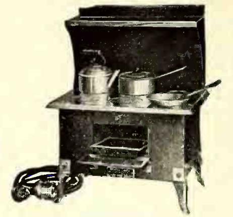
If the project shown in this photo looks dangerous to you, well, that’s probably because it is dangerous.

WARNING:  Do not construct the worm shocker shown on this page!  This is not a construction article.  It is an interesting historical look back at an earlier time when people didn’t worry quite so much about things like electrocution.  

If you ignore my advice, don’t sue me if something goes wrong (and that goes for your heirs, as well).

This illustration appears in the 1958 edition of the Electronic Experimenter’s Handbook, published by Popular Electronics.  It is exactly what it appears to be, namely, an AC line cord attached to two metallic probes.  One of the probes has rubber tape near the wooden handle.  The other one has not yet received this gesture toward safety.

Another warning:  If you insist on building this contraption, you must not plug this probe directly into an outlet.  It is plugged into a circuit which provides a small amount of safety.  If plugged directly into household current, it would be positively lethal, instead of just extremely dangerous.  (In fact, if you insist on doing this, it would be a good idea to use a plug rated at 120 volts, but one that does not fit into the normal household outlets, lest someone sees this one part and decides to plug it in to see what it does.)

With all of my earnest warnings out of the way, I’ll disclose what this is. It isn’t a torture device, at least not one for humans.  It’s actually part of a worm catcher, a labor-saving device that will bring earthworms to the surface for easy collection.  It does so by sending household current through the soil.  You stick the probes into the ground, about 3 feet apart, and then plug the probes into the accompanying power supply (and not directly into a wall outlet).  The worms will experience the discomfort of electrical current passing through them, and in an effort to escape, they’ll come to the surface where you can harvest them.

The accompanying article describes two power supplies. The first one consists of little more than two ten-watt light bulbs, one in series with each side of the AC line. The whole circuit is mounted in a wooden box. “Wood was used in this case because of its insulating properties.”

This circuit will undoubtedly trip a modern GFCI outlet. (And by code, any outside outlet should be protected by a GFCI.) Therefore, it probably wouldn’t work today.   I’m not going to explain why it wouldn’t work.  If you don’t know, then you should definitely not build either of these until you’ve brushed up on your electrical theory.

The second circuit is slightly safer, because it includes an isolation transformer. It’s still dangerous, because you’re still playing with 120 volts. It simply eliminates a few of the many possible methods of lethal electrocution. Like the other model, it drops the line voltage somewhat by passing the current through two light bulbs, in this case a 75 watt and a 25 watt in parallel. Since these bulbs probably wouldn’t glow brightly enough to see if the unit is energized, there is a test switch to temporarily remove the 75 watt bulb from the circuit. When the test button is pushed, the 25 watt bulb will provide a visual cue that the probes are correctly in place and the worms are on their way to the surface.

The article does contain a few safety warnings of its own. One of the descriptions starts with the self-evident comment that “the safety factor is the biggest problem involved in the use of house current.” It also warns: “Don’t take any chances by moving the probes when the unit is turned on.”  If the energized probes are safely underground, the effects will presumably be felt only by the worms.  And since the soil is not a perfect conductor, it’s probably not lethal to the worms.  But if the probes are out of the ground while energized, then they pose a hazard to humans in the area.

The editors also add the caution: “Do not attempt to modify either of these circuits. If wired according to the schematics, they will provide [somewhat] adequate protection from the LETHAL 117-volt a.c. household line.”

One warning that’s not mentioned in the article bears repeating.  It notes that if the ground is dry, then watering the ground first could improve performance.  This stands to reason, since damp soil is obviously more conductive than dry soil.  But it also highlights the fact that damp shoes (or bare feet) are better conductors than dry shoes.  So if you insist, despite my warnings, to attempt this method of worm collection, please make sure you’re wearing dry non-conductive shoes.

And remember:  Kids:  Don’t try this at home!


Click Here For Today’s Ripley’s Believe It Or Not Cartoon


1955 Pop ‘Tronics One Tube Receiver

1955PEonetube

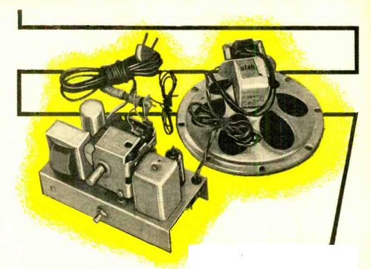
Sixty years ago this month, the October 1955 issue of Popular Electronics carried the plans for this one-tube broadcast set.  Even though it had only one tube, it was capable of driving a loudspeaker, thanks to the fact that the tube, a 1D8-GT, was actually three tubes in one.  In consisted of a diode, which was the radio’s detector, a triode, which served as the first AF stage, and a power pentode which drove the speaker.

So even though the set used a single tube, it was the equivalent of a crystal set with two stages of audio.  The article notes that the set gave good performance on strong local stations with just a few feet of wire for an antenna, and that it was able to pull in more distant stations with an outside antenna and ground.

The set was powered by a 1.5 volt A battery and a 90 volt B battery.  The pictorial diagram here1955PEonetubePictorial, more than the schematic, shows the simplicity of the little set.

A piece of wood, 8-1/2 by 5 inches, serves as the base, and the controls and speaker are mounted in place with right-angle brass brackets.  Terminal strips are used for the battery, antenna, and ground connections.


Click Here For Today’s Ripley’s Believe It Or Not Cartoon


Homemade Rectifiers, 1909-1935

Modern bridge rectifier.


Today, if you need a rectifier, it’s a fairly easy matter to buy one. One like the the one shown here will handle 1000 volts and 50 amps, and will only set you back a few dollars. Smaller ones for transistorized circuits can be had for pennies.

In 1935, however, it was a different matter, and parts were not so readily obtainable. Radios would typically use a vacuum tube rectifier, and for other applications such as battery chargers, a “dry” rectifier would commonly be used. In the 1935 Allied Radio Catalog, a “dry” rectifier has a catalog price of $3.73. A full-wave vacuum tube rectifier, the Raytheon BH, has a catalog price of $2.46. These prices don’t sound like a lot, but this was the middle of the Great Depression. And a silver dollar then was worth about the same as a silver dollar today. The only difference is that back then, you had to hand over an actual silver dollar for each dollar on the price tag.

1935 homemade copper oxide rectifier.

1935 homemade copper oxide rectifier.

It’s not surprising, therefore, that someone might decide to make their own. And Popular Mechanics 80 years ago this month, October 1935, showed how. It included circuits for a battery charger, a 6-volt “A” battery eliminator for a radio, and an A.C. voltmeter.

The finished product wasn’t particularly efficient. It required 16 volts AC in order to put out 6 volts DC. A rectifier consists of two dissimilar metals, and in this case, it made use of copper washers, one side of which was oxidized to form copper oxide. The washers were sandwiched between lead washers to form the necessary junction and keep them tightly fixed together.

The copper was oxidized by holding it over a gas flame, either from a bunsen burner or a gas stove. Then, it was left to cool, after which one side was carefully sanded with emery cloth. The pieces were then sandwiched together, with bakeline on the outside layer. The finished product was a bridge rectifier consisting of four diodes.

Building your own rectifiers was nothing new. In the early days of radio, even bigger rectifiers were needed. As I reported in an earlier post, in 1923, T.E. Nikirk, 6KA, solved the problem by building a rotary rectifier. It used a 3600 RPM synchronous motor, meaning that the motor revolved 60 times per second, just like the AC current. Attached was a spinning disk which served to reverse the polarity twice per cycle. In comparison, the 1935 “dry” rectifier seems tame.  Interestingly, the silicon rectifier at the top of the page probably has about the same ratings as 6KA’s massive spinning contraption.

1909 Chemical Rectifier.

1909 Chemical Rectifier.

More common in the early days of radio was the “wet” chemical rectifier, such as the one shown here from a 1909 issue of Popular Electricity.
It consisted of diodes made out of glass jars, each containing lead and aluminum electrodes, in a solution of ammonium phosphate.  A similar rectifier for use in a CW transmitter is described in a February 1921 QST article by P.J. Furlong, 1FF. For the electrolyte in his eight jelly jars, he used Twenty Mule Team Borax.

The modern silicon rectifier seems like a trivial component, and I don’t suppose I would try to save a few pennies by making my own.  But it comes under the category of things that it’s nice to know are possible.  You can make your own rectifier, and these old pioneers of electricity and radio showed that it was possible.

Click Here For Today’s Ripley’s Believe It Or Not Cartoon


Lee DeForest Designs the ANTI-AD, 1930

DeForestAntiAd

Dr. Lee DeForest is, of course, best known as the inventor of the audion, or triode tube. But he had many other inventions to his credit. For example, a few months ago, we featured the 1950’s Arizona fallout shelter/ham shack of William A. Rhodes, W7PYH (later W7KLA). It turns out that DeForest was co-inventor along with Rhodes of an electronic light amplifier with applications in astronomy and television.

And 85 years ago, we see what some might consider to be DeForest’s greatest invention, the “ANTI-AD,” a remote control device for squelching annoying radio advertisements. DeForest describes the device in the September 1930 issue of Radio News, wherein he laments “the tendency of the present radio broadcast programs to degenerate more and more into crass commercialism and to devote a steadily indreasing proportion of the time to exploiting the merits of every conceivable commondity from tooth-paste and cigarettes to household furniture and diamond rings.”

While remote control sets were coming onto the market, DeForest notes that they came with the nuisance of having a cable between the radio and the easy chair, over which “the missus and the children invariably trip.”

Instead, DeForest came up with the entirely wireless solution to the problem. The radio’s antenna lead is connected to the device shown here, which contains a selenium cell, one tube, and a relay. When the offending commercial interrupts the program, the listener simply shines a small flashlight, “which can be had in very ornamental form” at the device. When the light hits the photocell, the antenna is disconnected and the radio silenced. The relay had a time delay which could be set to correspond to a typical commercial length.

“When the announcer begins to tell the health benefits of his cigarette,” the listener simply gives the unit a quick flash, knowing that at the approximate end of the commercial, the device will reset and the program resume.

DeForest concludes that the “Anti-Ad adds to real radio enjoyment and greatly extends the number of hours throughout the month when the radio set is in operation. It should therefore be received with open arms by the entire radio industry.”  But perhaps it wasn’t, since ten years later, he wrote in an open letter to the National Association of Broadcasters:  “What have you done with my child, the radio broadcast? You have debased this child, dressed him in rags of ragtime, tatters of jive and boogie-woogie.”


Click Here For Today’s Ripley’s Believe It Or Not Cartoon


1975 Calculator Hardware Hack

The calculator complete with the new added functions.

The calculator complete with the new added functions.

In the early days of electronic calculators, one common IC was the MM5737, which supported four functions and eight digits. Its big brother, the MM5738, was slightly more advanced, since it included a single memory, a constant function, a percent function, and a battery-saving feature that would turn off the display after about 60 seconds.

What gave early hardware hackers (long before the term was invented) something to do was the fact that many calculator manufacturers stocked only the MM5738, even though some of their calculators didn’t make use of the extra functions. The cost of the chips was about the same; they simply didn’t wire in all of the functions on the less expensive “four banger” calculators.

Someone at Popular Electronics noticed this, and figured out how to add the hidden features to the less expensive models, which was revealed in the September 1975 issue.  The first step was to determine which chip was contained inside, and this could be done from the keyboard, without even opening up the case. This was because the MM5738 had the ability to peform repeated squares. From the keyboard, you simply had to enter 3, x, =, =. If the display said 81, then there was an MM5738 inside. If the display said 9, then the calculator used the more basic MM5737, and no modification was possible.

The author acknowledged that there would be no economy in trying to find a keypad with the added buttons. Instead, he proposed mounting four pushbuttons on the side of the case, to serve as the MS (memory store), MR (memory recall), K (constant), and % (percent) keys. He performed the modification on a Novus model 850.

I earlier wrote about the Novus model 650, an even more bare-bones model that lacked a decimal point. I suspect it used the same chip, and a similar procedure could have added it. The 650 had a retail price of $19.95 when it came out in 1974, but was down to $8.88 by December 1975.

Armed with the information in this article, owners of one of these very basic calculators could beat the system and save a couple of dollars by upgrading to a more advanced model by themselves.

Click Here For Today’s Ripley’s Believe It Or Not Cartoon