Distance Education for Disabled Students, 1941

1946JuneService

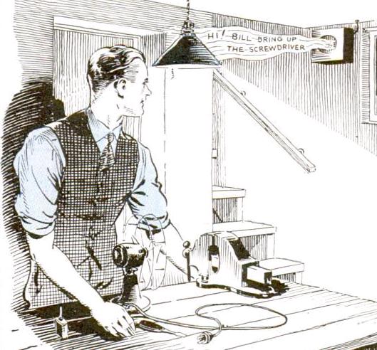
Shown here is Mary Ellen Lydon, a teacher at Monroe Junior High School in Mason City, Iowa, instructing her class 75 years ago. In addition to teaching the students in the classroom, you will notice an intercom sitting on her desk. With this device, she was able to bring instruction to shut-in students at home, as described in the June 1941 issue of Service magazine.

Mason City student Mary Brown receiving her instruction at home.

Mason City student Mary Brown receiving her instruction at home.

The article reported on the experiences of fifteen rural Iowa school districts which, mindful of their responsibility to furnish education to physically handicapped children, relied upon this method. The program began in Newton, Iowa, in 1939, when the school was unable to provide teaching facilities to a disabled student. The experiment proved a success. In particular, there was such a benefit to her morale and physical condition that she was able to return to school before the end of the semester, despite an earlier prognosis that she would be disabled for an entire year. In many cases, the shut-in students excelled academically, and in one cases, the shut-in was elected class president.  In total, over a hundred sets were in use in Iowa classrooms.

The equipment consisted of standard commerical intercoms, along with transformers to allow their use over standard leased telephone lines. At school, as the students went from class to class, the intercom was brought to the next teacher’s room to allow the student to attend the full schedule of classes.  The cost of equipment was about $40 per pupil served, and the phone lines were leased at a monthly rate of $1.25 for the first quarter mile, and 75 cents per each additional quarter mile. The longest distance served was about five miles.

Click Here For Today’s Ripley’s Believe It Or Not Cartoon


1916 Portable Transmitter/Receiver

1916JuneElectricalExperimenter

A hundred years ago this month, the June 1916 issue of Electrical Experimenter magazine carried the plans for this portable wireless set. The author noted that now that summer was in sight, the progressive radio amateur was making ready for experiments with portable equipment. However, it noted that too many sets were made of extra or discarded equipment, with disappointing results.

The set shown here promised good results with an antenna of 150-200 feet, 30 feet high on each end. The receiver was a crystal set with no power needed, and the transmitter would provide many hours of service with six internal flashlight batteries of 4.5 volts each, wired in parallel. Provision was made for six external large dry cells in series. With this power source, the set would produce a 1/32 inch spark. A test buzzer for setting the detector was separately powered with a 1.5 volt dry cell.

The author noted that the receiver pulled in NAA in Arlington, Virginia, in New York City, a distance of 275 miles, and that longer distances could be covered. The transmitter was capable of getting out about two miles, or even five or ten if an audion detector was used at the other end.

The total weight of the set, mounted in a suitcase, was about 14 pounds, and the total cost was about $15. The article notes that this cost was low enough to bring it within the reach of every wireless club or Boy Scout troop.

The author of the article was Milton B. Sleeper (1896-1963), who later went on to publish a number of magazines, such as High Fidelity and FM/TV. About the time of this article, Sleeper was working for Lee De Forest, and he later became a close associate of Major Edwin Armstrong.

The full schematic of the set is shown below, although it contains one perplexing omission.

1916JuneElectricalExperimenterSchematic

My first reaction when looking at the schematic of the transmitter was to wonder what made the coil spark, since the primary is connected only to DC, meaning that other than the instant when the key was depressed, there would be no voltage on the secondary.  The article, however, mentions the spark coil’s vibrator, which is not shown in the schematic.  The primary would have an series with it an interrupter, which would rapidly turn the coil on and off, resulting in a square-wave AC current, which would make the transformer work, resulting in a higher voltage on the secondary, sufficient to create a spark.  Since a manufactured spark coil was used, the schematic doesn’t show this detail.

A more complete diagram of a similar transmitter, from a 1920 issue of Electronics World shows the internal wiring of the spark coil:

1920ElectronicsWorld

When the key is pressed, the power from the battery energizes the primary of the spark coil.  In so doing, the magnetic field pulls open the primary vibrator contact, which kills the power to the primary.  With the magnetic field gone, the vibrator contact closes, once again energizing the coil.  The wiring is exactly the same as an electrical bell or buzzer, which operates on the same principle.  This causes the primary of the coil to repeatedly turn on and off, generating a square wave, which induces a larger voltage in the secondary winding, and that voltage is large enough to generate a spark.

Click Here For Today’s Ripley’s Believe It Or Not Cartoon



1956 Vocaline Model JRC-400 CB Transceiver

1956VocalineCover

Sixty years ago, the familiar Class D Citizens Band at 27 MHz was still a couple of years away. Class B Citizens Band on 465 MHz had been authorized for a number of years, but as the June 1956 issue of Popular Electronics  pointed out, the service hadn’t gained traction due to equipment requirements:

Equipment for the Citizens band (radio -telephone) must meet specifications set forth by the Federal Communications Commission. To pass these specifications, the equipment must be examined and ap- proved by the FCC in its laboratories. Because of this cumbersome arrange- ment (although fully justified), the design of Citizens radio equipment has for a number of years taken a back seat. The ice has been broken by the Vocaline Model JRC-400 transceiver, which brings Citizens band communication facilities within the reach of everyone’s pocket. After a manufacturer secures FCC approval, he may then produce identical units on an assembly line basis.

The magazine promised further reviews in upcoming issues, but included some observations about the Vocaline unit, which could operate on either 117 volts AC or 6 volts DC. The magazine’s field test showed 100% reliable ranges of 1.5 miles in a metropolitan area or 3 miles in open areas. Out in the country, weak signals were fully readable up to six miles.

1956VocalineAntennaThe same issue of the magazine carried this ad for the transceiver, showing its retail price of $69.75. The antenna was available separately, and consisted of a quarter-wave ground plane which could be affixed to a vehicle’s roof with large suction cups.

1956VocalineAd

A schematic of the set is available online and reveals that the set used three tubes. A 6AF4 served as superegenerative detector and the oscillator for the transmitter. For audio on both transmit and receive, a 6AV6 and 6AS5 were used. The power supply included a vibrator for DC operation, and included a selenium rectifier.

Click Here For Today’s Ripley’s Believe It Or Not Cartoon


Battle of Jutland, 1916

HMS Queen Mary. Wikipedia photo.

Today marks the 100th anniversary of the Battle of Jutland, which took place May 31-June 1, 1916.

The battle between the German and British fleets in the North Sea was the largest naval battle of the war, and the only full-scale clash of battleships.  The German plan was to lure the British fleet on German terms, but the British got the upper hand largely because of intercepts of German radio signals.  Both sides ultimately claimed victory, but the loss of life on both sides was staggering.  British losses were 6784, and German 3039.

TownshendAmong the dead were numerous wireless operators, and they were eulogized in the August 1916 issue of Wireless World.  Among them was H.B. Townshend, wireless operator aboard the battle cruiser Queen Mary. He had passed the wireless examination at the age of sixteen, and was informed at the time that he was the youngest wireless operator in the Fleet.


Read More at Amazon


Click Here For Today’s Ripley’s Believe It Or Not Cartoon


Memorial Day

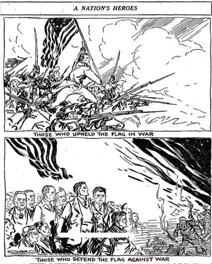
The United States declared War on Germany on April 6, 1917. While the first American troops didn’t arrive in Europe until June of that year, this would be the last Memorial Day while America was still at peace. The following editorial appeared in the Chicago Tribune a hundred years ago today, May 30, 1916:

1916MemorialDay

Click Here For Today’s Ripley’s Believe It Or Not Cartoon


3QF, Merchantville, NJ, 1916

1916MayQST

This drawing of a well equipped amateur station of a century ago appeared in QST, May 1916. It shows the station of J. Donald Haig of Merchantville, N.J.  The sketch, drawn by Mr. Haig, shows the sending set containing Leyden jar condensers, rotary spark gap, and large oscillation transformer.  The receiver is shown to the left.

QST didn’t give Mr. Haig’s call sign, but according to the 1916 call book, the call was 3QF, and the station was located at 118 E. Maple Avenue in Merchantville.


Click Here For Today’s Ripley’s Believe It Or Not Cartoon


1941 Aetna Model 421

19410528Seventy-five years ago, someone looking for an inexpensive radio could get one of these at Walgreen’s for $5.99. This is a bare-bones four tube superheterodyne sold under the Aetna name, which was Walgreen’s house brand, which could have come from a number of factories in the Chicago area. This ad appeared in the Milwaukee Journal, May 28, 1941.

The set appears to be Aetna model 421.  It tunes up to 1700 kHz, meaning it would tune the newly expanded broadcast band, as well as some police calls.  With the war less than a year away and the end of radio production, this set would probably remain in service for the duration.

Click Here For Today’s Ripley’s Believe It Or Not Cartoon


Stromberg-Carlson New World Console, 1946

1941May27Life

Shown here from the May 27, 1946, issue of Life Magazine are newlyweds Sally and Ed enjoying their new Stromberg-Carlson New World console. The magazine advertisement describes it as one of the magnificent radio-phonographs as new in performance as in cabinet styling. The picture was just part of a short drama presented by the ad. Dad (apparently Sally’s father) was almost the forgotten man. Sally and Ed were about to be married, and Dad was resigned to the fate of fathers–paying the bills and keeping out of the way.

But then he remembered how much Sally enjoyed her smart little Stromberg-Carlson Vagabond portable. And then he thought about how much Ed loved music, and how fond he was of his own family’s recent purchase of a Stromberg-Carlson Empire console.

So Dad became the real best man by presenting Sally and Ed with their very own Stromberg-Carlson console. The ad reminded the reader that they could do the same and become the hero of any wedding, birthday, anniversary, or any other occasion.

Click Here For Today’s Ripley’s Believe It Or Not Cartoon


Lucile Fairbanks and GE Musaphonic Console, 1941

1941LucileFairbanks

In May 1941, the American economy was beginning to boom. Radio Today magazine alerted radio dealers that business indexes were peaking, men were going back to work in increasing numbers, defense jobs were putting money into workers’ pockets. In short, people had money to spend and were earning it.

The magazine showed radio dealers how to go after this money. The magazine noted that extra shoppers were coming to town, and one of the radio man’s jobs was to get them next to bigger radios, like actress Lucile Fairbanks with the GE Musaphonic console shown here.

Click Here For Today’s Ripley’s Believe It Or Not Cartoon



1931 Electronic Television

1931ElectronicTVImageShown here is one of the very earliest examples of an image sent by electronic television. It appeared 85 years ago, in the May-June 1931 issue of Television News, in an article by Baron Manfred Von Ardenne, whom the magazine identified as the “famous European televsision expert.”

Von Ardenne noted that the cathode-ray tube had “long been proposed for television reception and has been used in many more or less successful laboratory experiments. In spite of these extremely
advantageous characteristics, television has thus far been obtained only with mechano-optical means.”  He then went on to discuss some of his improvements.

His system involved using a cathode-ray tube as part of the transmitter.  A film was placed between the tube and a photo-electric cell.  Thus, the tube in the camera could be synchronized with the tube in the receiver scanning at the same rate.  Depending on the configuration of the electronics, the resulting image would be either the positive or the negative of the original film.  A diagram of the system used for transmission is shown here:

1931ElectronicTVtransmission

Von Ardenne made the first public demonstration of this system in August 1931 at the Berlin Radio Show. He successfully transmitted pictures in 1933, and his system was used in the German television service starting in 1934. Regular broadcasting began in 1935 and continued throughout the war.

Bundesarchiv Bild 183-K0917-500, Prof. Manfred v. Ardenne.jpg

Von Ardenne in 1930. Wikipedia photo.

After the war, von Ardenne made contacts with the Red Army and found his way to the Soviet Union, where he was made head of Institute A. He was initially asked to participate in the Soviet atomic bomb project, but declines, realizing that his participation would prevent his return to Germany. Instead, he worked on isotope enrichment. His work included development of an electron microscope, for which he was awarded the Stalin Prize. With the prize money of 100,000 rubles, he purchased the land for a private institute in East Germany, where he was allowed to return in 1954. From 1963 to 1989, he served as a member of the Volkskammer, the East German parliament.  At the time of his death in 1997, he held about 600 patents.

Click Here For Today’s Ripley’s Believe It Or Not Cartoon