This ad appeared 80 years ago in Radio Craft magazine, April 1946. We decided to get at the real backstory of how this young woman found her way into a capacitor ad, so we asked Google Gemini, who delivered this logical explanation:
In 1946, the world was finally trading in its olive drab for something with a bit more chrome. But for the boys down at the local radio shop, the “atomic age” was more than just a headline—it was sitting right there on the counter in a tailored trench coat.
Her name was Sarah, though behind her back, the consensus was that she was a total bombshell. She had a way of walking into a room that made every vacuum tube in the shop feel like it was about to red-plate.
She stepped up to the counter, reached into her pocket, and pulled out a cigarette. Before anyone could reach for a Zippo, “Sparky” Pete leaned over with his soldering iron. He offered the hot, tinned tip with a steady hand; she leaned in, took a light, and blew a cool plume of smoke toward the “No Smoking” sign.
“My portable,” she said, her voice like velvet. “It’s got a hum that won’t quit.”
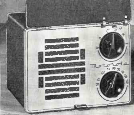
She reached into her other pocket and pulled out a radio so small it seemed impossible. It was a sleek little set, the kind of miracle the magazines promised once the factories stopped making tanks.
Sparky popped the back off the set and whistled. “I see the problem, Miss. Someone tried to fix this with some old-fashioned, oversized wax paper caps. They’re crowding the chassis. In a set this small, that’s just asking for a meltdown.”
He reached for a yellow-and-black box on the shelf labeled Solar. He pulled out a handful of “Little Giant” MINICAPS. They were tiny, gleaming, and looked like they belonged in a watch, not a radio.
“You see these?” Sparky said, holding one up to the light. “These Solars are the real deal. During the war, they were the only thing tough enough and small enough to go into the proximity fuses of the actual bombs we dropped. If they could survive being shot out of a cannon and still trigger an explosion at the right microsecond, they can certainly handle your favorite swing station.”
He went to work, his iron dancing across the terminals. He cleared out the bulky, outdated components and tucked the Solar units into the tight corners of the chassis. They fit like they were born there.
“The military spent millions perfecting these so they wouldn’t fail under fire,” Sparky explained as he snapped the case shut. “Now, they’re the only reason you can fit a five-tube performance into a pocket like yours.”
He tuned it to the local station, and the music came through crystal clear—no hum, no hiss.
Sarah tucked the radio back into her coat. The lines of her pocket remained perfectly smooth, thanks to the space saved by the Solar tech. She gave the boys a wink that was more dangerous than a high-voltage rail.
“Thanks, boys,” the bombshell said, heading for the door. “It’s good to know the same stuff that won the war is now keeping me in tune.”
“Well,” Sparky muttered to the guys, “I guess it’s true what they say: it takes a set of those ‘bomb’ capacitors to keep a bombshell from having a blowout.”
Google Gemini was also kind enough to supply these Amazon affiliate links. If you make any purchase after using one of these links, this website earns a small commission.
Gear Up Your Workbench
If you’re looking to do some “bombshell” level restoration of your own, here are a few essentials for the modern radio bench:

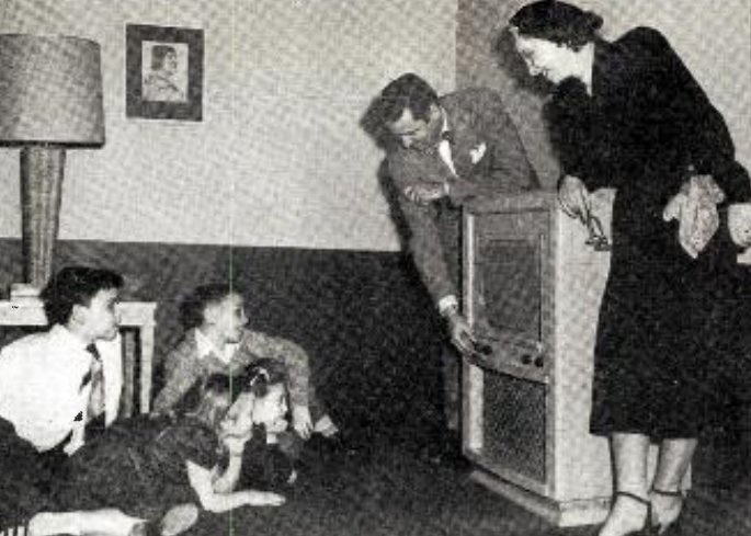 The youngsters in this picture are now octogenarians, but 75 years ago, they were the test audience for “The Chimps.” They are shown in the April 23, 1951, issue of Broadcasting, which explains that the series of 13 15-minute films had been produced by Bing Crosby Enterprises, and featured chimpanzees in “western and whodunit dramas.”