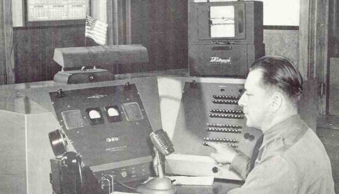
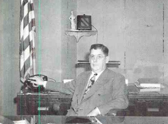
St. Paul Police Sgt. Hans Peterson.
Shown above, 70 years ago, is Sgt. Hans Peterson of the St. Paul, MN, Police Department, at the console of the city’s mobile radio system. The system was described in detail in a two-part series appearing in the February and March, 1951, issues of FM-TV-Radio Communications magazine, authored by the city’s Commissioner of Public Safety, Robert F. Peterson.
Peterson notes that, as in most other cities, greatly increased demands had been placed upon the police department since the war, due to added services, as well as additional crime and juvenile delinquency. And with the development of long-range aircraft, the city found itself closer to Russia than the cities on the east coast, making civil defense a concern. “Obviously, more manpower is indicated, but in St. Paul our 40-hour week and limited budget make any substantial increase in personnel out of the question.” Therefore, the city turned to technology, in the form of a modern radio system, to increase efficiency of officers. The system also handled traffic for the city of West St. Paul and the Ramsey County Sheriff’s Department.
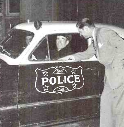
Engineer Bob Morrison standing beside police cruiser. Selective call light is visible above center of windshield.
The system consisted of equipping 53 police vehicles, as well as fire stations and vehicles, with dual-frequency radios with selective calling capability. All outgoing calls were handled on 159.09 MHz from a console at the Public Safety Building. A leased telephone line led to the transmitter and receiver atop the First National Bank Building. The transmitter room was, understandably, kept locked at all times, and also had a CO2 fire suppression system installed. The door and fire system had monitors that were linked back to the main control point, so that the dispatcher would be aware of any intrusion or fire.
Normally, all units operated on 159.09 MHz. But the mobile units were all equipped to transmit on a secondary frequency of 158.97 MHz, which was continually monitored by the dispatcher. This allowed mobile units to make emergency calls even during longer broadcasts from the dispatcher.
A key element of the system was the selective calling ability. The console shown above was equipped with dozens of switches, one for each mobile unit. One of these could be switched on to selectively call any car. Normally, officers in the squad would be listening to the radio at all times. But previously, if they had to get out of the car to perform their duties, they were out of service for further calls. For example, if an officer were out of his squad car investigating a traffic accident and a robbery occurred just around the corner, there would be no way to alert the officer.
Selective calling provided a solution. When an officer was out of his car, he could still be alerted by a light mounted above the windshield, or perhaps a horn. These were connected the the selective calling system. If the officer was needed, the dispatcher would flip the switch, the light would come on, and the officer would know there was a priority call.
A duplicate console was connected. Shown below, radio operator Art Tweet is shown at this console. The radio operator was responsible for system operation, but in rush hours, he could assist the dispatcher.
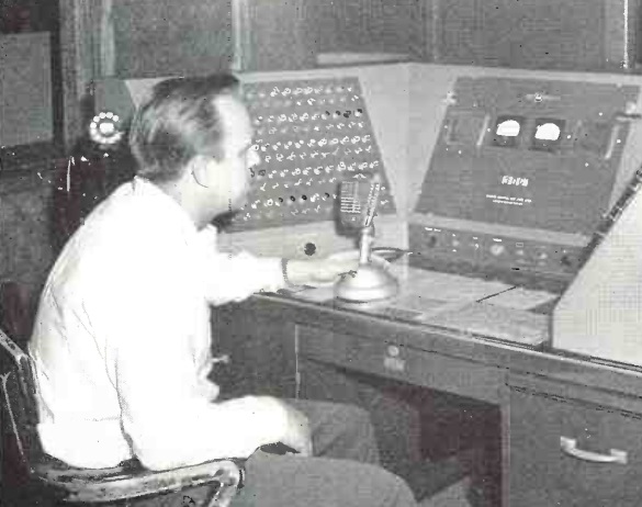
Radio Operator Art Tweet
Police Chief Charles J. Tierney.
Fire Chief William H. Mattocks.
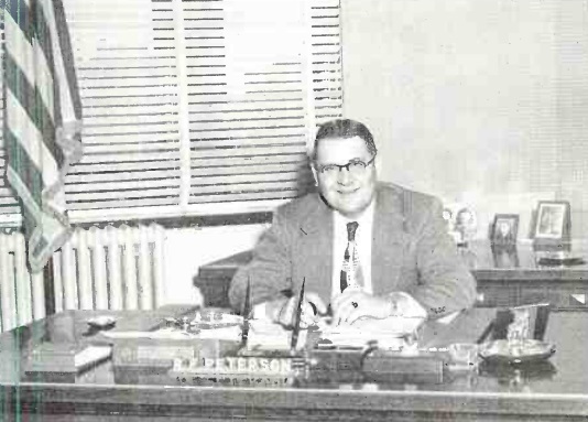
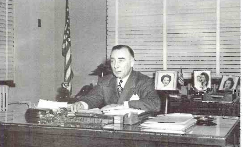
Commissioner of Public Safety Robert F. Peterson.
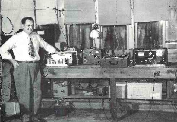
Superintendent of Radio L.A. Ginther.
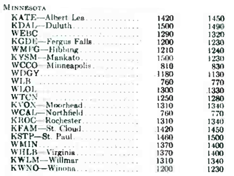 As we’ve previously written, on March 29, 1941, most broadcasting stations in the United States changed frequency, as the top of the dial moved from 1500 kHz to 1600. This listing shows all stations in Minnesota at that time. The first column shows their old frequency, and the last column shows the new frequency, many of which still look familiar today.