Category Archives: Science fair ideas

Science Fair Idea: Eddy Currents

1936decps

Eddy currents in solid core (left) and laminated core (right). Wikipedia image. This file is made available under the Creative Commons CC0 1.0 Universal Public Domain Dedication.

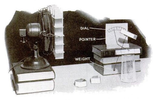
This simple experiment from eighty years ago shows how to experimentally verify the existence of eddy currents in the core of an electromagnet or transformer.

A coil of wire through which house current is passing is wound over two cores. One half is a solid piece of iron, and the other half consists of pieces of wire bundled together. The magnetic field in the coil, which changes direction 60 times per second, sets up eddy currents in the solid core, and the result is that it becomes noticeably warm. In the core consisting of wire, the currents are broken up, and the effect is not noticed.

Of course, it goes without saying that the aspiring scientist should be careful using household current in an experiment. But as long as all of the connections are properly made and insulated wire is used, the experiment is perfectly safe, and would make a good science fair experiment.

The image is from the December 1936 issue of Popular Science.

In transformers, eddy currents are undesirable, since they cause unwanted heat and inefficiency.  However, they have some practical applications, such as levitation and braking.


Science Fair Idea: Homemade Cardboard Box Speaker

1966octradiotvexp

The young scientist or engineer looking for a relatively simple but interesting project for the science fair could construct the homemade permanent-magnet speaker shown here.  It appeared fifty years ago this month in the October-November 1966 issue of Radio-TV Experimenter.

The speaker is constructed inside a cardboard box, which also serves as the sounding board (which the article incorrectly calls a “cone,” which it would be in a normal speaker).

The only other components, aside from a few pieces of cardboard and glue, consist of a permanent magnet and wire. Just as in a commercially manufactured speaker, a coil of is mounted on a form surrounding the magnet. When an audio signal is applied to the coil, it and the top of the box are made to vibrate.

The 1965 plans call for a magnet from a burnt out speaker, and this would still be a possibility.  These days, a more prolific source of powerful magnets would be from the drives of defunct computers, as shown in this video:

Suitable magnets are also available from Amazon or many other sources.  These plans call for a coil of 75 turns of 30-gauge enamel wire, although the exact wire size is not critical. The original plans call for using the speaker with a radio or television. The simplest way to make the connection to a modern radio or MP3 player would be through the headphone jack. Another option would be to use an inexpensive audio amplifier such as the one shown below:

The use of an audio amplifier would also allow the use of a homemade microphone, such as one of those shown in an earlier post.  And for another somewhat more complex homemade speaker (or microphone), see this post.

Click Here For Today’s Ripley’s Believe It Or Not Cartoon


Science Fair Project: Atomic Frog Clock

1916septwirelessage

Here’s a picture of the time signal coming from the Eiffel Tower a century ago, as shown in the September 1916 issue of Wireless Age.

They were the results of experiments by one Dr. Lefeuvre, professor of physiology at Rennes University. The experiments were apparently carried out a few years prior, before the war, since they were also reported in the February 1913 issue of Popular Mechanics.

1913pmfroglegThe Eiffel Tower signals were received at a distance of 230 miles, and most remarkably, the mechanism for recording them was a frog’s leg, using the apparatus shown here.

Even though Prof. Lefeuvre conceded that there was no practical application to his system of “muscle writing,” it was regarded as a highly interesting laboratory experiment.

The sciatic nerve of the leg, cut below the knee, was spliced into the audio output of the receiver, with one end of the leg pinned securely to a base, and the other end connected to a lever. A pen recorded the impulses on the rotating drum.

Unfortunately, the “frog’s leg and its nerve do not retain their sensitivity very long,” precluding commercial application.

The experiment was, of course, an updated version of Luigi Galvani‘s 1780 experiment showing the frog legs could be made to twitch by application of static electricity.   Aspiring young mad scientists could probably develop an interesting science fair project along the same lines.  Instead of the Eiffel Tower time signals of a century ago, modern students in America could use the signals generated by WWV.  The now common “atomic clocks” rely on signals from sister station WWVB.  A bright student could quite easily construct a similarly accurate version, using the same user interface developed by Galvani over two centuries ago.  You might get some inspiration from this video:

Click Here For Today’s Ripley’s Believe It Or Not Cartoon


Piezoelectrics For Your Time Travel and Post-Apocalyptic Needs

Completed piezoelectric speaker from 1968 article.

Completed piezoelectric speaker from 1968 article.

A few weeks ago, I wrote about some plans for homemade microphones from 1945. One was very crude but easy to duplicate. But one was quite sophisticated, and could be made at home by growing a piezoelectric crystal from a saturated solution of Rochelle Salt.

The piezoelectric microphone is particularly intriguing because it should function equally well as a piezoelectric speaker.  For this reason, it has an interesting application, albeit perhaps not one that is immediately practical.

Being Prepared for Inadvertent Time Travel

The knowledge of how to build such a speaker could come in handy in a couple of situations, at least one of which is probably unlikely.  The first situation would be that of inadvertent time travel.  If you get caught in a time warp and sent to the past, it would be wise if you could make the best of a bad situation and be able to “invent” some technological devices.  (And as I’ve previously written, having a WikiReader in your pocket would make the situation much more bearable.)  And as a loyal reader of this blog, it stands to reason that one of the technologies that you could “invent” would be radio.


While there are no documented cases of this ever happening, the science fiction literature is full of examples.  Probably the oldest example is Mark Twain‘s A Connecticut Yankee in King Arthur’s Court.  Other examples include 1632 by Eric Flint and the Island in the Sea of Time series by S.M. Stirling.

Cobbling together a transmitter would be relatively easy, as long as the time period into which you were deposited had some rudimentary industries.  You’ll need some wire for winding coils and putting up an antenna, some metal for building capacitors and a spark gap, some acid for making batteries, and a few other bits and pieces that should be readily available in the Middle Ages.  With a bit of ingenuity, you should be able to come up with a transmitter with a range of hundreds of miles.

And with the exception of one component, a suitable receiver would be relatively easy to make.  Once again, you’ll need some wire for the coil and antenna, a few pieces of metal for fabricating other parts, and something to serve as a detector.  The detector would be quite simple.  The most common material, which would give good results, would be a chunk of Galena (lead ore).  If you find yourself in an area where this mineral is unavailable, there are many substitutes, as discussed in my earlier posts (this one and this one) about “foxhole radios” or my earlier post about emergency wartime crystal sets.

The one part, however, that will be difficult to procure is a suitable earphone.  If you’re lucky enough to be transported back in time after the invention of the telephone, then your problem is partially solved.  A telephone receiver will have an impedance that is too low for your receiver, but by rewinding the coil, you should be able to come up with a suitable headphone.  If the telephone hasn’t been invented yet, you can of course take the honors and invent it.  But if you want to jump ahead to radio technology, you’ll need to fabricate a suitable headphone to hook up to your radio.

This brings us back to the piezoelectric microphone we discussed earlier.   This type of microphone works equally well in either direction:  It can change electrical impulses to sound, as well as working the other way around and changing sound into electrical impulses.  Therefore, if you build a piezoelectric microphone, you can hook it up to your crystal set and listen to that transmitter you put on the air.

As discussed in my earlier post, the piezoelectric microphone/headphone should be relatively straightforward.  All you need, in addition to the scraps of metal you already procured, is a piezoelectric crystal.  And the article linked there gives you the basics of growing one.  In addition to water, all you will need is Rochelle Salt, also known as potassium sodium tartrate tetrahydrate.  This compound was first prepared in 1675 by Pierre Seignette. So if your time travel lands you after that date, you should be able to procure it. Of if it’s about 1675 and you’re anywhere near La Rochelle, France, you would be advised to look up Monsieur Seignette and collaborate with him on the project.

If you arrive before 1675, all hope is not lost. According to this site, you can whip up a batch using the ingredients cream of tartar and washing soda.  Cream of tartar is a byproduct of the wine making process, so it should be available at any time after the invention of wine, which dates back to antiquity.  So as long as those ingredients are available, you should be able to recreate radio.

An alternative method of building the headphone is described in the book The Voice of the Crystal by H. Peter Friedrichs.  This is a magnetic headphone which would require a very fine gauge of insulated wire, but a good jeweler of almost any era should be able to help you procure the components.

Rebuilding Civilization After a Collapse

The other time one would need to recreate radio technology would be after a collapse of society.  There are billions of radios in existence, any many more component parts, so it is very unlikely that you would need to start from scratch.  Even after hundreds of years of dark ages, many relics of our current technological society would still be available to provide usable parts.  This scenario is discussed in detail in the book The Knowledge: How to Rebuild Civilization in the Aftermath of a Cataclysm by Lewis Dartnell, which I previously reviewed.

The most abundant source of headphones for your post-apocalyptic crystal set would probably be the microphones from the billions of cell phones currently in existence.  In most cases, these are probably piezoelectric, and would work well for a crystal set headphone.  (The billions of stereo headphones and earbuds probably wouldn’t be of much use, since they are too low an impedance to work properly with a crystal set.)

Science Fair Project

Even if you don’t anticipate time travel or TEOTWAWKI (The End Of the World As We Know It), a homemade speaker or microphone could be part of a most impressive science fair project.  Even very young students could fabricate the simple three-nail microphone shown in my earlier post.  And more advanced students will be capable of making speakers or microphones that rival commercially available ones.

A More Refined Version of the Piezoelectric Speaker

Near perfect crystals from 1968 article.

Near perfect crystals from 1968 article.

The 1945 piezoelectric microphone linked in my original post is probably suitable for all of your time travel or post-apocalyptic needs.  However, a more refined version, shown at the top of this page, is from the May-June 1968 issue of Elementary Electronics.  While the 1945 article probably gives enough detail for the experimenter to grow a crystal and put it to work, the 1968 article goes into much greater detail.  It gives detailed instructions on growing the crystal, and the completed crystals, shown here, turn out nearly perfect.  In particular, the 1968 article gives detailed instructions on starting with a seed crystal and maintaining the temperature of the saturated solution as the crystals form.  While the 1945 article would probably result in a usable crystal looking like a piece of rock candy, the details in the later article result in a crystal that can be further ground to dimensions that would make it quite sensitive.

Construction details of 1968 piezoelectric speaker.

Construction details of 1968 piezoelectric speaker.

The construction details of the final speaker are shown above.  The crystal is ground and polished to about 1/16 inch in thickness, and then sandwiched between two pieces of aluminum foil.  (If your time travels take you to a time when aluminum was still considered a precious metal, substitution of other metal shouldn’t present a problem.)  A current applied to the two pieces of foil causes the crystal to vibrate.  The author of the 1968 article used the cone of a defunct 12 inch radio speaker, which could be replaced by some other type of cone.  For use with a crystal set, the large cone might prove a detriment, since the crystal set might not be putting out enough audio to set it into vibration.  Constructing some sort of headphone would probably be more suitable for a crystal set.

The photo above shows a matching transformer, but this would not be necessary for use with a crystal set.  The example shown in the 1968 article was designed to replace a standard low-impedance permanent magnet speaker.  The high impedance of the piezoelectric speaker would be perfectly suited to the output of a crystal set.

For even more details on growing crystals, the author of the 1968 article recommends the book Crystals and Crystal Growing by by Alan Holden and Phylis Morrison, which is still available and in print.  And if you’re just looking to make a crystal set and want to buy a piezoelectric earphone (or other needed parts), you can find them on my crystal set parts page.


Click Here For Today’s Ripley’s Believe It Or Not Cartoon


Science Fair Idea: Homemade Microphones

1945Microphone0

For the aspiring mad scientist, young or old, the November 1945 issue of Popular Science shows how to make several homemade microphones.  If you’re a student looking for a science fair project, then building your own microphone is probably going to impress the teacher more than a homemade volcano.  While other kids might even put together electronic projects, it’s unlikely that very many of them will put together individual electronic components.  And since most people think of microphones as sensitive and complicated instruments, you’ll probably be the only one to think of it.  You’ll discover that most of them are quite simple to construct, although there’s no need for you to share that little secret with the judges.

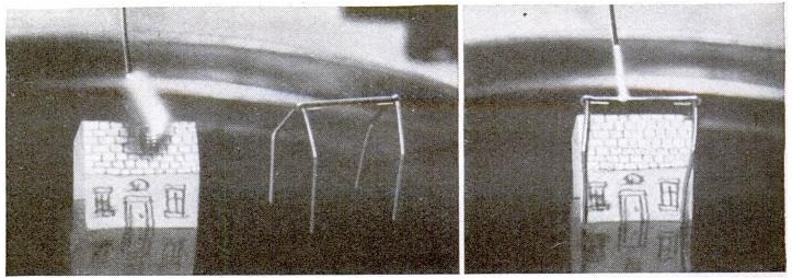
1945Microphone1The first design, shown here and in the photograph at the top of the page, is simplicity itself.  It consists of little more than three nails, one resting precariously on top of the other two.  When struck by sound waves, the top nail vibrates, causing a slight change in resistance.

1945Microphone2The second design, shown here, is only slightly more sophisticated.  It is a carbon button microphone, and consists of carbon granules in a small container, such as the cap of a ketchup bottle.  As sound strikes the granules, the resistance changes.  This setup requires a slightly higher voltage, but will give you considerably more audio output.  The carbon granules can be obtained by cracking open a carbon-zinc battery (the cheap kind), removing the carbon rod in the middle, and crushing it up.  A double-button design is also shown for the advanced student.

1945Microphone3A homemade dynamic microphone is shown here.  It consists of a coil of wire mounted between two magnets.  When the coil moves as a result of sound, the microphone becomes a tiny electric generator producing an AC current in time with the sound.  Unlike the earlier designs, which simply varied the resistance, this one requires an amplifier to amplify the tiny current generated.  In 1945, this probably posed a bit of a problem.  But today, you can easily connect it to a cheap audio amplifier such as this one and get plenty of audio to impress the judges.  You can also simply plug the microphone into the microphone input of a computer.  Another variation of the dynamic mike, also described in the article, is the ribbon mike, which substitutes a thin ribbon of foil for the diaphragm.

1945Microphone4The final, and most advanced, microphone described in the article is shown here.  This is the piezoelectric or crystal microphone, which your teacher would probably tell you is impossible to make at home.  But your teacher is wrong, as shown by this 70 year old article.  You simply grow yourself a suitable piezoelectric crystal and arrange it as shown here.  While it might sound intimidating to grow a crystal, this is actually the same thing your less advanced peers are doing by making rock candy as their science fair entry.  Instead of using sugar to make the crystal, you use Rochelle Salt (potassium sodium tartate). Your chemistry teacher probably has a dusty bottle in the lab. If not, you can simply buy some on Amazon.  Like the dynamic microphone, this one is hooked up to an audio amplifier.

If you’re a student, your teacher is probably tired of homemade volcanoes, potato clocks, and other scientific curiosities that he or she has seen a hundred times before.  Your homemade microphone(s) will be most impressive.  And even if your school days are behind you, making these simple microphones will be quite rewarding.


Click Here For Today’s Ripley’s Believe It Or Not Cartoon


Science Fair Ideas: Homemade Batteries from 1965

HomemadeBattery3

When the aspiring young mad scientist is looking for ideas for the science fair, someone invariably suggests making a homemade battery. Making a battery is a fairly simple proposition. All you need are two dissimilar metals and an electrolyte. A common choice for electrolyte is a mild acid such as lemon juice, and copper and zinc make good dissimilar metals. No matter how badly you construct the thing, a little bit of electrical current is bound to flow, and you can probably coax a little bit of light out of a light-emitting diode (LED) or even power a small electronic device such as a digital clock.

A good choice for the kids who aren’t as smart as you are.

In fact, for students with limited scientific abilities, you can just go out and buy yourself a Potato Clock kit. You simply open the box and jab the electrodes into a potato, and the potato juice serves as the electrolyte. It’s completely safe, since I can hardly think of any chemical more benign than potato juice. If you drop the potato on the floor, you don’t need to bother calling the haz mat team. And unless you screw up horribly, the clock will instantly come to life. There’s nothing wrong with the humble potato clock, but if you’re reading this looking for ideas, you probably want to come up with something a bit more spectacular. And while you’re at it, you probably want to use chemicals slightly more dangerous than potato juice.

So you might want to go back in history a bit when adults weren’t quite so concerned with hazardous chemicals, and use something slightly more powerful in making your battery. You can go back in time fifty years, when adults let their responsible children play around with slightly more dangerous chemicals such as household bleach, often referred to by its most popular brand name, Clorox. Not only will you have more fun, but you’ll wind up with a much more powerful battery, suitable for powering much bigger electronic devices.

For details on how to put the battery together, you can go to page 98 the Fall 1965 issue of Elementary Electronics.  That article describes two batteries that you can make at home, both of which are hundreds of times more powerful than the one running that other kid’s potato clock.

Warning:  Bleach really is a dangerous chemical.  You need to be careful with it, and keep it out of the reach of children who are not as smart as you are.  If you get any on your clothes, your mom will be mad.  If you get any in your eyes, you’re facing a major medical emergency.  Your mom is probably right when she tells you, “you can put an eye out with that.”  Ask your parents and/or teacher for permission.  If they balk at the idea, ask them to read the article about how to make the battery.  To show how responsible you are, show them that you read the Material Safety Data Sheet (MSDS).

Homemade battery using drops of bleach.

Battery using drops of bleach.

The article shows how to make two batteries.  The first one, while much more powerful than the potato, is “more of a novelty than a practical device.”  It is shown here, and consists of fifteen sets of aluminum strips and copper wires. The metallic pieces are arranged in a circle around a piece of Plexiglas. The copper and aluminum are close together, but not touching.  When ready for use, a drop of bleach is placed on each one.  When the last drop of bleach is added, the connected radio or other device springs to life.  If measured with a voltmeter, the complete battery will put out about 15 volts.  However, this drops when there’s an actual load, and 15 cells is about right to power a radio that normally calls for 9 volts.

Unlike the potato battery, this one will run a radio for several minutes.  But the article concedes that it’s more of a novelty.  Therefore, the article goes on to describe another more powerful battery.  The bigger one is even suitable for use around the house in case of a power outage.  If the power is out and you’ve used up the last battery, there’s probably still a bottle of bleach down in the laundry room, good for hundreds of homemade batteries.

HomemadeBattery2

Homemade battery using ice cube tray.

The larger battery is constructed in a plastic ice cube tray.  You use six of the individual compartments, so you can cut the ice cube tray in half and make two batteries.  Each compartment of the tray contains one piece of aluminum and one piece of copper.  You simply fill each compartment with bleach, and you have enough power to run a radio for several hours.  When the battery finally goes dead, you pour out the old bleach and replace it.  You can re-use the battery hundreds of times before the aluminum finally gets worn away completely.

Voltaic pile similar to the 1799 version. Wikipedia photo.

With either battery, you have essentially recreated the work of Allesandro Volta, who invented the Voltaic pile in 1799.  He was eventually able to build a battery large enough to administer an uncomfortable electric shock.  Until the electric generator came along in the 1870’s, anything that required electricity (such as the telegraph or telephone) was powered by batteries similar to those created by Volta.

Armed with this fifty year old article, a bottle of bleach, and a few pieces of scrap metal, you can now make your own Voltaic pile.  You’ll get to use dangerous chemicals.  You can generate significant amounts of electrical power.  Perhaps you can even administer uncomfortable electric shocks to your friends, teachers, and parents.

You’ll have the most interesting project at the science fair.  And the kid who goes home with a participation ribbon for his potato clock is going to be pissed.

Check out my other science fair ideas, some of which are slightly dangerous.

Click Here For Today’s Ripley’s Believe It Or Not Cartoon


Science Fair Idea: Measuring the Speed of Sound

Measuring the speed of sound with an oscilloscope.

Measuring the speed of sound with an oscilloscope.

In an earlier post, I gave some ideas for young mad scientists to employ for science fair projects. Another idea comes from the pages of the April 1966 issue of Radio Constructor, a British electronics magazine. The article explains two methods of experimentally measuring the speed of sound. One of those methods requires an oscilloscope, but the other one requires only an AC voltmeter.

Measuring the speed of sound with an AC voltmeter.

Measuring the speed of sound with an AC voltmeter.

Fortunately, the young experimenter of today can duplicate either of these experiments quite easily. For the version of the experiment requiring an AC voltmeter, most modern digital multitesters would be very suitable, and they are often available for next to nothing. The following examples are currently available at Amazon:


Harbor Freight
often has multitesters on sale, or occasionally for free. They’re also available inexpensively at WalMart.

The oscilloscope is more expensive, but still a lot less expensive than 1966. For example, this USB Oscilloscope can be used with a PC for a reasonable price. And while a bit more do-it-yourself work would be required, this USB oscilloscope is also very inexpensive.

The only other equipment required is an audio signal generator (for which you could easily use your computer’s sound card) and an audio amplifier, such as this one. The other required parts, such as speakers, can easily be scrounged up.

Using either method, it’s fairly simple to measure the wavelength of the audio signal. Since the frequency is known, it’s then an easy matter to calculate the speed of sound, which would be frequency times wavelength. The possibilities for using this as part of a science fair project are unlimited. For example, it would be possible to measure the speed of sound under various conditions, such as with differing barometric pressures or altitudes. By waterproofing the speakers, it would be possible to measure speed of sound in water, and compare it to the value in the air.

In any event, your poor teacher is probably tired of seeing paper mache volcanoes, and will probably be quite impressed at your abilities.

Click Here For Today’s Ripley’s Believe It Or Not Cartoon


The Flame Audion

One interesting footnote in Radio History can be found in Alfred Powell Morgan’s 1914 book Wireless Telegraph Construction for Amateurs. This is the Flame Audion detector, shown below:

FlameAudion

Morgan describes it thus:

The simple but sensitive form of detector illustrated in Fig. 119 is not of practical value for commercial work, but is very interesting as the progenitor of the audion, and provides a good field for amateur investigation. Its only drawback is that the gas flame is very difficult to keep steady and every flicker registers as a sound in the telephone receivers.

A Bunsen burner using coal gas furnishes the flame, and a salt of an alkaline metal heated in the flame, the ions. The hydroxides of csesium, potassium and sodium give the best results in the order named.

The salt is contained in a piece of trough-shaped platinum foil, about 3/8 inch long and 1/16 inch wide. This trough is made the cathode or negative of the telephone circuit and placed in the outer oxidizing flame just above its juncture with the interior reducing flame and must be kept incandescent. The upper electrode .or anode is a piece of platinum wire about  1/16 inch above the trough.

The arrangement and construction of the detector is clearly indicated by the drawing so that it is unnecessary to go into details. The block, E which fits on the tube of the Bunsen burner, is made of fiber. Two double binding posts, D, are fastened to E to support the rods, R, which are fitted at the tops with binding posts, B, into which the electrodes may be clamped.

Twelve dry cells are connected with a multiple point switch so that an electromotive force of 6-18 volts, varying in steps of one cell at a time, may be secured. The flame is best provided with a mica chimney to protect it from drafts. By keeping plenty of salt in the trough and carefully adjusting the voltage, this detector may be made marvelously sensitive.

This type of detector was the inspiration for the Audion tube. The effect was discovered by the Audion’s inventor, Dr. Lee DeForest, in 1903. DeForest writes in 1947 about this discovery:

I used a Bunsen burner, locating within the flame two platinum electrodes, one of which was connected through the telephone receiver to a dry battery, and thence to the other platinum electode. I enriched the flame with sodium, or common salt.

I then found that when the electrodes were properly located in the gas flame the signals from my spark transmitter were distinctly audible in the telephone receiver. I made countless experiments with this phenomenon; and to prove definitely that the effect was not acoustic but electrical, I connected one of the flame electrodes to my antenna, the other to the ground, and actually obtained wireless signals from ships in New York Harbor.

Radio-Craft, January, 1947

deforestdiagram

DeForest’s Diagram of the Flame Audion Circuit

DeForest applied for a patent in 1905, and was issued U.S. Patent 979275 for the flame detector in 1910.

DeForest wrote about the flame audion himself a number of times. For example, see his articles in Western Electrician, November 3, 1906; the February, 1916, edition of Popular Mechanics; the January, 1947, issue of Radio-Craft.

He wrote a more complete scientific paper which was published in the Transactions of the American Institute of Electrical Engineers in 1906.

DeForest is occasionally criticized for not really understanding what was going on inside the triode. This criticism isn’t really fair. It was later discoverd that the Audion acted as an amplifier. It was quite imperfect as an amplifying tube, because it did not have a complete vacuum. But from reading DeForest’s writings, it is clear that he never intended to invent an amplifying tube. He was working on a detector, and the ionized gas within the tube (which wouldn’t have been there if it had been a true vacuum tube) was responsible for this capability. The amplifying ability was, indeed, a lucky accidental discovery. But particularly looking over the 1906 paper, it’s clear that DeForest was an extremely gifted engineer, and he is worthy of the credit he has received for his advancement of radio in the early years.

It seems to me that students looking for an interesting science fair project might be inspired by DeForest’s work. It combines both fire and electricity. Since it had no reasonable commercial use in the early 1900’s, there was no good reason for scientists to pursue it. But it seems to me that interesting things might be going on inside that flame.

DeForest used platinum wire, which is rather expensive. On the other hand, the cost isn’t entirely out of line. For about $20, you can buy enough Platinum Wire to construct the detector. Platinum foil would be prohibitively expensive, but there doesn’t seem to be any reason why the salt needs to be contained by the platinum. It seems to me that two platinum wire electrodes could be used. And while DeForest used platinum, there doesn’t seem to be any evidence that he experimented with other metals. Would copper perform the same function?

The flame audion was used as a radio detector by DeForest. But earlier scientists had shown that the flame would conduct electricity, a fact that is obvious from the flow of current through the gap. What flames provide better conductivity? Salt is added presumably because it ionizes better than just the fuel and air alone. It would be a relatively simple matter to measure the conductivity of different ionized materials.  Variations in the flame can be heard in the headphones, so for the purpose of making a sensitive radio detector, it’s probably necessary to have a very constant flame.  But for many applications, it seems to me that an ordinary candle would suffice.

(For more science project ideas, see my review of the book Radio Science for the Radio Amateur.)


Book Review: Radio Science for the Radio Amateur by Eric Nichols, KL7AJ

At the Sooland Amateur Radio Association hamfest, I was the winner of $50 worth of ARRL books.  After perusing the available options, and deciding that my 2010 Handbook was current enough for my needs, I decided to get Radio Science for the Radio Amateur
by Eric Nichols, KL7AJ.

The book bears the rather steep list price of $27.95, although it’s available at Amazon for a bit less. Overall, it was a good read, although I think I would have been somewhat disappointed if I had paid the list price. I suspect the price had something to do with the handful of one-star reviews on Amazon.

Nichols is a regular poster on the forums at qrz.com, and the book’s writing style is a similar level of informality.  Some of the Amazon reviews point out that he seems to jump all over the place from topic to topic, and this is true.  However, the book isn’t intended to be a scientific treatise about any particular subject.  Nor does the book give many construction details.  What the book does do, and the scatterbrained style actually does well, is give the reader some ideas about real scientific experimentation that can be done by amateur radio operators.  It whets the appetite and lets the reader do some more research about what is possible.   The book doesn’t really teach you how to do anything, but it does teach you that a number of interesting activities can be done.

In no particular order, here are some of the insights that I got from the book:

1.  It’s possible to build a plasma chamber at home.  I’m not sure exactly what I would do with it once built, but he does suggest some ideas.

2. One can purchase data acquisition modules relatively inexpensively, and these allow you to interface a computer to an analog voltage source (such as a receiver S-meter, a photocell, or a thermocouple) so that the computer can easily collect data for later number crunching.

3. Amateur radio offers some real possibilities for distributed science. My own short story, Clint’s Best DX, concludes with an author’s note saying that the story was impossible. In the story, the hero discovers extraterrestrial life with his 6-meter beam. I explain that this is impossible, because the signal strength is just too weak for earthbound antennas.  (For an explanation of why, see this interesting NASA article, which also explains whether there are aliens watching reruns of I Love Lucy.)  The book got me re-thinking that conclusion.  If properly synchronized, it’s possible to distribute an antenna over widely separated points on earth.  If Clint were to use such a distributed antenna instead of his 6-meter Yagi, then perhaps he could listen to the farm reports from Canis Minor after all.

4.  Even the lone ham can do quite a bit of ionospheric research in his own back yard, and can probably do much more with some sort of distributed data collection.

The conspiracy buffs will be disappointed by this book, because it turns out that HAARP (the High Frequency Active Auroral Research Program) has a pretty mundane purpose, but makes use of some pretty interesting science.  It turns out that a lot of mixing of radio signals can take place in the ionosphere.  This is due to something called the “Luxembourg Effect”, which is explained pretty well in this 1935 article.  The powerful longwave transmitters of Radio Luxembourg (and Gorky, Russia) were found to cross-modulate the signals of stations on a higher frequency located further away along the same path.  The strong longwave signals were modulating the signal of the higher frequency station in the ionosphere as it passed over the longwave transmitter.

HAARP, as it turns out, was mostly involved in using this phenomenon as a cheap (by military standards) method of generating low-frequency signals.  It can be quite a task to generate a strong low frequency signal in order to communicate with submarines.  But if you want to generate a 20 kHz radio signal, one way to do it is to generate two HF signals 20 kHz apart.  The ionosphere will serve as the mixing stage, and the result is a 20 kHz signal being transmitted from the edge of space.  Since this signal penetrates sea water, the submarines can copy it.  Unfortunately for the conspiracy buffs, I can’t think of any easy way to use this phenomenon to generate earthquakes, hurricanes, or any of the other phenomena that are associated with HAARP in the minds of some.

I think the best use of this book is to inspire aspiring young mad scientists.  While not disclosing too many details, I think this book suggests a number of science projects that are well within the capabilities of a bright high school student.  So if you are a bright high school student looking for an interesting science fair project, I think you’ll get some good ideas from this book.  While your classmates are busy building their potato battery clocks or making a volcano out of vinegar and baking soda, you can be doing some actual science.  What do you think your teacher will find more interesting, a homemade model of a volcano, or your measurements of the motion of the ionosphere?  If you need to build some tangible device, then I suggest that a homemade plasma chamber, made out of a plexiglass tube, nails, and a pump from an old refrigerator, will probably be a bit more impressive than the potato clock that your classmate offers.

The price of the book is indeed a bit steep for the impoverished student.  If you can’t find a used copy on Amazon, you can speak to your friendly librarian and ask them to order a copy.  If your local library is also too impoverished to buy it, you’ll impress your local librarian to no end if you walk up to the reference desk and ask them to get a copy through “interlibrary loan”.  You simply print out the listing from WORLDCAT, which shows the closest library with a copy.  Your local librarian will request a copy from that library, and in a couple of weeks, it will be delivered for you to check out.  Librarians thrive on doing this sort of thing, and they will be absolutely thrilled to learn that a student actually knows what interlibrary loan is, and actually gives the librarian the excuse to engage in the process.

For now, I glossed over the chapters on Smith Charts and wave polarization.  There appears to be a lot of good material there, but it will require a bit more study than the quick read I was able to give most of the other chapters.  For once, however, I do have some understanding of what is meant by the “characteristic impedance” of a feedline.  A feedline is nothing more than in infinite number of tiny inductors in series, along with an infinite number of capactiors in parallel.  This tiny components have both an inductance and a capacitance.  And, of course, any time you have an inductance or capacitance, you also have an inductive reactance and capacitive reactance.   And when I re-read that chapter, I have no doubt that I’ll have some understanding of how those give the characteristic impedance of the feedline.

Perhaps I would have been a bit disappointed if I had shelled out $27.95 for the book.  But overall, I got some good ideas from the book and I’m pleased that I selected it as my hamfest door prize.