We recently featured a 1958 Soviet kerosene powered radio and lamented the fact that similar products are not available today. It turns out, however, that we were wrong.

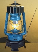 First, a Facebook comment to our original post alerted us to the Lufo lamp, shown here. This is a kerosene lantern, apparently developed as part of a UN project to provide radio receivers for Africa. The heat from the lamp operates a Peltier effect device which powers the built-in AM FM radio.
These don’t appear to be manufactured currently, but they are reportedly available in Europe if you look hard enough.
There is, however, one device on the market currently, and it doesn’t even require kerosene! At Amazon, you can purchase a wood-powered USB charger that uses the same principle. You can then charge your phone using sticks gathered from your yard.
The USB charger appears to be a bit of an afterthought, but also appears to be fully functional. It appears that the Peltier device power supply is intended mostly to power an internal fan that increases the efficiency of the stove. But it also provides usable power, which is available from the USB socket.
The stove also includes an internal 2600 mAh lithium-ion battery to store the charge. According to the Amazon reviews, the stove itself works extremely well. According to one review, the stove will boil a pint of water in about four minutes, which is quite good for a stove burning nothing but small twigs. The stove is useful for charging a phone or other device. The fan speed appears to be a trade-off. With the fan on high speed, the stove runs most efficiently, but it also uses most of the current that is produced. It appears that the best compromise for generating electricity is to run the fan on low speed.
For the do it yourselfer, it seems that producing a similar device should be relatively easy and inexpensive. The Peltier elements are readily available on Amazon. You can also order direct from China with free shipping at this link. They’re normally intended for use in applications such as 12-volt coolers, where an electric current is run through the device, where it produces a difference in temperature between the hot side of the device and the cold side. But this is a case where the physics works the same with a minus sign in front of the equation: If you generate a difference in temperature, this will cause electric current to flow.
You’ll probably need more than one, and you’ll probably have to experiment with wiring them in series (to increase voltage) and parallel (to increase current) to get sufficient power. You’ll also need some kind of heat sink mounted on the cold side. The device will have maximum output when the temperature difference between the two sides is greatest. So you need to get one side as hot as possible while keeping the other side of the thin device as cool as possible.
Once you have sufficient voltage and current, you can hook the output to a 12 volt USB charger. Even if you don’t have a full 12 volts, most such chargers are little more than a voltage regulator, so as long as your output is more than 5 volts, you should have a fully functional USB power connection.
To use your new power supply to listen to the radio, you could add the small portable shown here. When batteries are available, you can use standard AAA batteries. During the day, you can run it with the built-in solar cell. And at night, you can plug it in to your wood burning charger with its USB port.

Of course, most of our readers will want to listen to shortwave, and will probably opt for this inexpensive USB-powered receiver which tunes AM, FM, and 4.75-21.85 MHz shortwave.
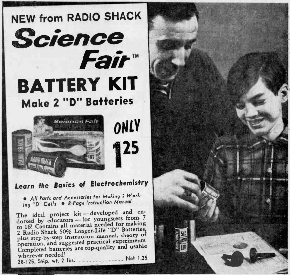
In addition to being useful for camping or emergencies, such a project would be excellent for a science fair project.