Category Archives: Radio history

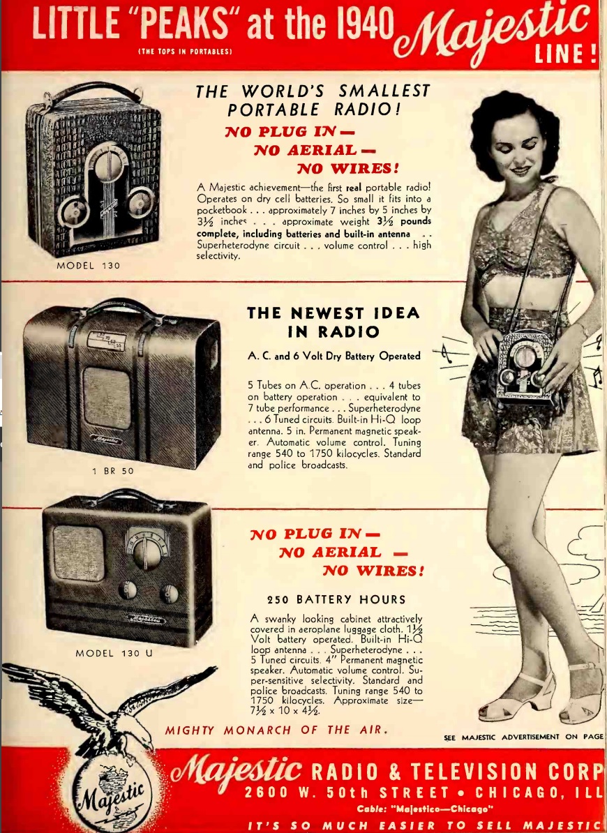
Majestic Model 130 Portable, 1939

1939JuneRadioTodayEighty years ago this month, the young woman shown here was pulling in some musical entertainment on her way to the beach, courtesy of her Majestic model 130 portable radio.  The “camera style” set, billed as the world’s smallest portable, featured a superheterodyne circuit, with a 3-tube lineup consisting of 1A7GT, 1N5GT, and 1D8GT, powered by a 60 volt B battery and a 1.5 volt battery to light the filaments.

The ad here appeared in the June 1939 issue of Radio Today.  You can see a restored example of the set playing at this video:


1949 Radio Hat

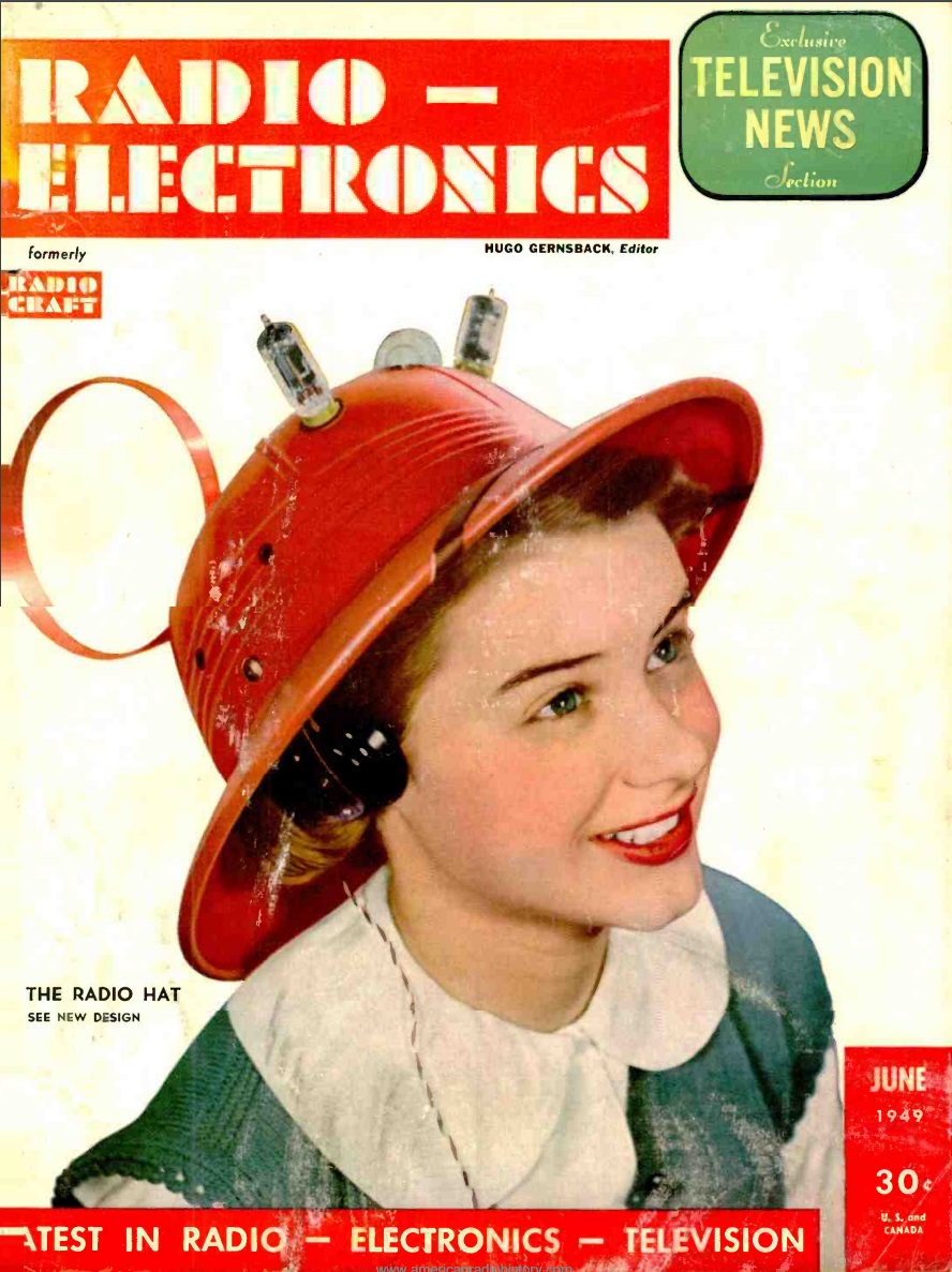
1944JuneRadioElectSeventy years ago this month, the cover of the June 1949 issue of Radio Electronics showed the very stylish and useful Radio Hat, a product of the American Merri-Lei Corporation of Brooklyn, New York. I’ve only seen one of these in person, and I was always curious as to how well it performed. The magazine put the set to a test, and declared it to be a good performer.

With a price of under $8, the editors assumed that the original market was for children. But for travelers or sports fans, the set was quite adequate for adults. The magazine reported that in New York, it pulled in all of the stations well, especially outdoors, and even performed quite well inside steel buildings. The hat weighed only 12 ounces and was adjustable. The batteries, a 22.5 volt B battery and two A batteries, were carried in a pocket and connected to the hat with a cord. An earphone was in the hat over the left ear, but it was possible to move it to the right.

The two-tube set used a 1S5 as regenerative detector, with a 3V4 amplifying the audio.  The tubes were coated in plastic to prevent them from shattering in their exposed position.

If the model wearing the hat looks familiar, it’s because she is a 15-year-old Hope Lange, who went on to become an actress, probably most familiar as Mrs. Muir in the Ghost and Mrs. Muir.  You can also read more about the Radio Hat at its Wikipedia article, which is based largely upon the Radio Electronics article.

1944JuneRadioElectschematic


1959 British One Valve Radiogram

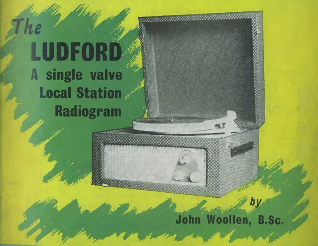
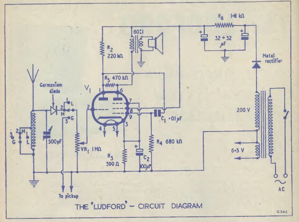
1959JuneRadioConstrSixty years ago this month, the June 1959 issue of British magazine Radio Constructor showed how to put together this one valve radiogram.  For readers on this side of the pond, that means a one-tube radio-phono combination.  A single ECL80 dual tube served as audio amplifier for both the radio and phonograph.  A simple crystal set using a germanium diode pulled in the local stations on either long wave or medium wave.

In addition to showing how to put together the simple circuit, the magazine promised that the cabinet work would be lucidly explained so that no difficulty would be experienced, even by a beginner.  A power transformer assured safe operation, and a single DP3T switch was used to select longwave, mediumwave, or gramophone.

1959JuneRadioConstrSchematic


Radio Direction Finding

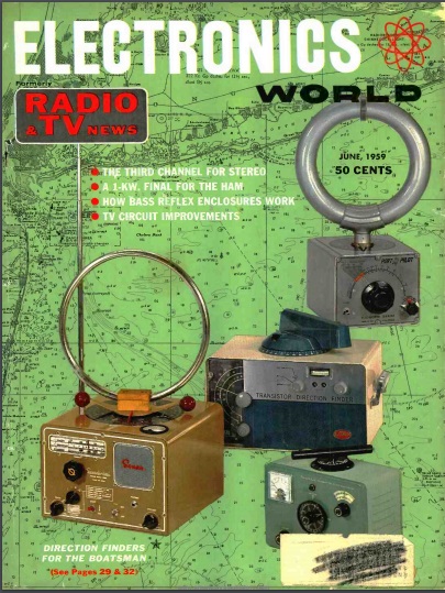
1959JuneElecWorldCoverSixty years ago this month, the June 1959 issue of Electronics World carried a good basic introduction to marine direction finding (DF).  The cover image shows a number of commercially made DF units, and the article explains how they work.

While the technology looks archaic, it actually still works quite well, and will continue to do so as long as there are AM radio stations on the air.  While commercial direction finders are no longer readily available, virtually any AM radio will work well, as long as the antenna is directional.  And if the radio has an internal loop antenna, it will be directional.

For example, the inexpensive portable shown at the right will perform very well.  (It’s available at Amazon at this link, but any other inexpensive portable will work just as well.)  You simply rotate the radio until the signal is the weakest.  At that point, the internal antenna (usually in parallel with the top of the radio) is in a straight line with a station.  You place a ruler on the map over that station’s location, and draw a line in that direction.  You repeat the process with a second station, and where the lines meet is your location.  You’ll need to orient the map, so if you don’t know what way is North, it’s a good idea to have an inexpensive compass.  And you don’t really need a ruler.  You place the map on a table oriented with the Earth–the top of the map facing North–and then use the top of the radio as your ruler.

1959JuneElecWorld

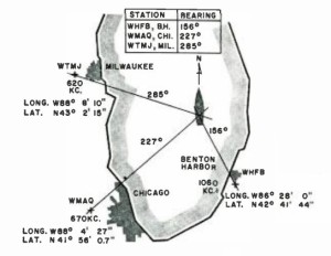
This method is surprisingly accurate.  It’s very easy to find your location within a mile, and with some practice, you’ll be able to narrow it down even more.  It’s not quite as accurate as GPS, but if GPS ever becomes unavailable for any reason, this is an excellent backup method.  The example shown at the left is typical.  By knowing the exact location of radio stations in Chicago, Milwaukee, and Benton Harbor, MI, the boat can find its location within a few hundred yards.

Radio station locations are shown on maritime and aeronautical charts.  You can also find the exact locations of AM radio stations from the FCC database.


Sparton Model 590-1 Portable, 1939

1939JuneRadioRetailing

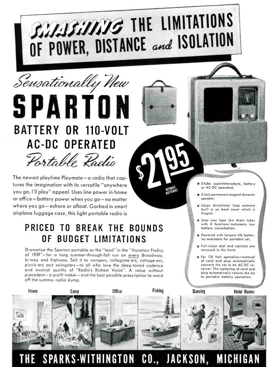
Eighty years ago this month, the June 1939 issue of Radio Retailing carried this ad reminding dealers that they should stock up on portables for campers, collegiate-ers, picnic-ers, and swingsters.

The set shown is the Model 590-1. The superheterodyne set featued a tube lineup of 1A7G, 1N5G, 1H5G, and 1A5G, with a 35Z5GT rectifier for use at home.  The set switched automatically from household current to battery by removing the line cord.


Amateur TV, 1959

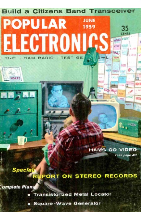
1959JunePE1Sixty years ago this month, the cover story of the June 1959 issue of Popular Electronics was all about the small but growing number of amateur radio operators on television. The 70 cm band had been allocated for TV, and pockets of hams were putting it to use.

Cameras were very expensive, and required a lot of studio lighting. So some hams were content to get on the air with a flying spot projector and slides, similar to the test device we featured earlier. An existing TV receiver was used to illuminate the slide, with a photocell picking up the image as each line was illuminated.


USS Squalus, 1939

1939JJune16RadioGuide

In drydock after salvage. Wikipedia photo.

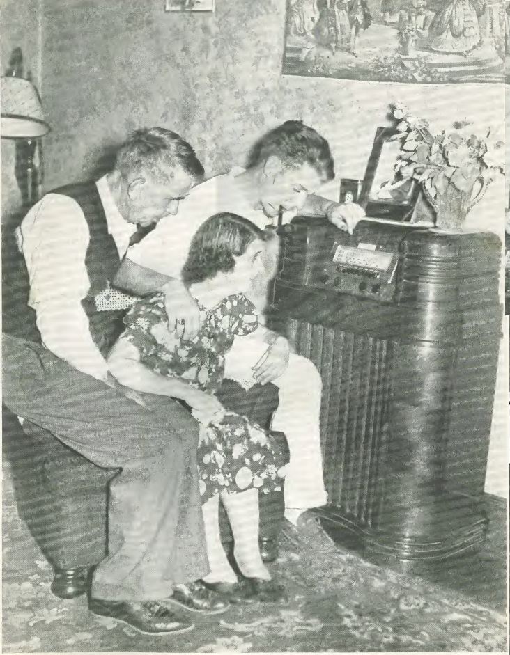
This picture above appeared 80 years ago today in the June 16, 1939, issue of Radio Guide. Shown is a Washington, D.C., family gathered around the radio, obviously clinging to every word of the news announcer. They are the family of William Isaacs, who was aboard the Navy submarine U.S.S. Squalus when it sank off the coast of New Hampshire on May 23, 1939, killing 26 crew members. The remaining 33 aboard (32 crew and one civilian) were rescued. The ship was initially in contact with a companion ship by telephone line to a buoy, and the men were rescued from 243 feet of water thanks to the McCann Rescue Chamber.

The ship was eventually salvaged, and went on to serve in the Pacific during World War II as the USS Sailfish.  The ship was scrapped after the War, but the conning tower, shown here, was preserved after the war as a memorial at Portsmouth Naval Shipyard.

The family shown here eventually received good news, as Isaacs was one of the men successfully rescued from the sunken ship.


Clock Radios: 1959

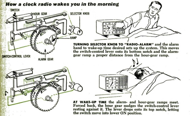
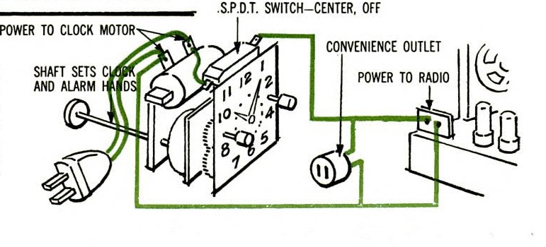
1959JunePSSixty years ago this month, the June 1959 issue of Popular Science explained how the ubiquitous clock radio worked, using a General Electric model as the example.  This model included a sleep feature which let the radio play when going to bed.  In the morning, the radio would first come on, followed by a buzzer ten minutes later.  It also included an outlet at the back for a small appliance.

According to the magazine, the clock radio first came out in 1947, and in the previous year, 2.3 million of the sets were sold by 25 different manufacturers.

1959JunePS2


1949 Two Tube Superheterodyne Portable

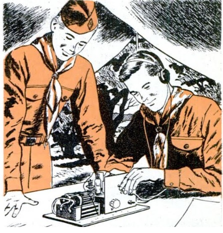
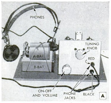
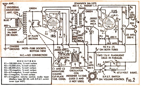
1949JunePM11949JunePM2The scouts shown above are taking a break from their campout to pull in some local broadcast stations on the two-tube superheterodyne receiver they constructing from the plans in the June 1949 issue of Popular Mechanics. The set used a 1R5 and a 1U5 tube and a 15 foot antenna to get good volume on the local stations. According to the magazine, the set rivaled any regenerative receiver, without the possibility of an annoying squeal.

According to the magazine, the rugged little set was ideal for camping or other knockabut use. It could be transported in a small cardboard container, or, if the builder preferred, in a cabinet.

The filaments ran off two flashlight batteries in parallel, with a 67.5 volt B battery.  For strong stations, a 45 volt battery could be substituted.

1949JunePMschematic


1938 New England Hurricane

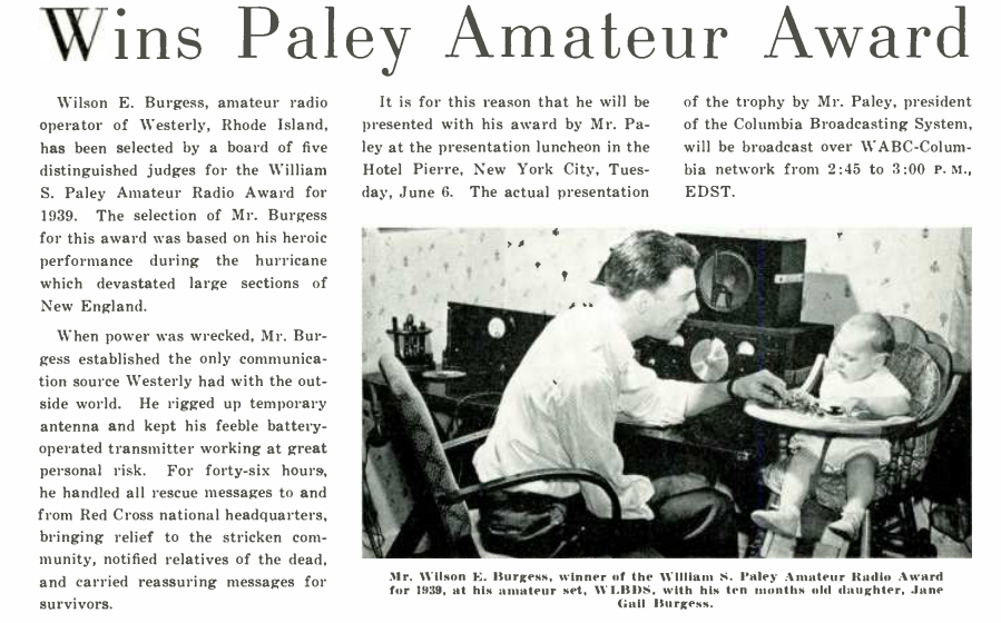
1944JuneRuralRadioThe article shown above appeared in the June 1939 issue of Rural Radio magazine, detailing an award to Wilson E. Burgess, W1BDS, for his work during the 1938 New England Hurricane.  The storm was one of the deadliest to ever hit New England and Long Island, with an estimated 682 killed.  It’s the strongest hurricane to hit New England in modern times, possibly eclipsed by the Great Colonial Hurricane of 1635.

While this article is short on details, more can be learned from Clinton DeSoto‘s 1941 book Calling CQ.

Rhode Island hurricane damage. Wikipedia image.

The storm was poorly forecast, and hit Burgess’s hometown of Westerly, R.I., with little warning the afternoon of September 21, 1938. Burgess was working as the manager of the appliance department at Montgomery Ward when the storm blew out the windows of the store. Panicked people were running up and down the aisles of the store. It soon became apparent that a hurricane was in progress.

He quickly collected a quantity of batteries and started for home on foot. He struggled up the street as trees fell around him. At the police station, he met up with another amateur, George Marshall, W1KRQ. Together, the set off toward Burgess’s home with the batteries. Eventually, they were able to hitch a ride on a county truck, but it was soon blocked by trees and they again had to continue on foot.

They eventually made it, but he found that the edge of his garage that had supported his antenna had been swept away. He went out in the 65 MPH winds to put it back up, and eventually had to settle for wrapping the wire around his house.
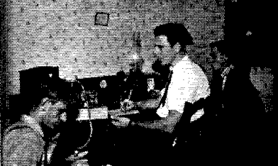
W1KRF, W1BDS, W1KRQ at the makeshift station.  QST, Nov. 1938, p. 12.

W1KRF, W1BDS, W1KRQ at the makeshift station. QST, Nov. 1938, p. 12.

By this time, of course, the power was out, and there was no way to power Burgess’s normal 600 watt transmitter. Working by kerosene lantern, the two men worked for two hours building a one-tube transmitter to use with the batteries carried from the store.  DeSoto reports that the windows had been blown out by this time, and daughter Jane Gail Burgess, shown in the photo above, then three months old, was crying in terror.

Finally, they had the transmitter and a makeshift receiver ready, and Burgess started putting out a QRR–the then-distress call. Unfortunately, nobody really knew that an emergency was in progress, and their weak signal simply wasn’t heard over the interference of a normal busy ham band. They moved their CW signal up to the phone band, reasoning that the CW signal would stand out there. The trick worked, and soon W2CQD in New Jersey answered the call, with W1SZ in Connecticut (QST managing editor) later taking over. For the next five days, the Connecticut station maintained contact.

Neighbors eventually got word to the local Red Cross that radio contact had been made, and the house soon became a center for relief activity. The first official message was to Red Cross headquarters in Washington, but that message was not accepted, since it was signed merely “Westerly Red Cross.” Eventually, the name of the local chairman was added, and the message was accepted.