Category Archives: Radio history

1920 Cigarette Ad: Ham Contacts Mars

1920Nov30PennsacolaJournal

This ad for Chesterfield cigarettes appeared in a number of papers, including the Pensacola (Florida) Journal, a hundred years ago today, November 30, 1920. The ad copy reads as follows:

Young Hiram Jinks
had tried for weeks
to talk to Mars
by Wireless.

He’d pounded his key,
calling “Mars, Hello, Mars,”
until his right biceps
was the village pride.
He hardly dared to sleep
lest he miss the call,
And say! One evening,
he got an answering buzz,
“yep, this is Mars.”
And Hiram shook all over
and stuttered back in Morse,
“have you any word,
for us on Earth?”

Quick came the answer.
“You can tell the world,
they satisfy!” Then silence.

Hiram ran to the corner store
and shouted in triumph.
“A message from Mars!
You can tell the world.
They Satisfy.”

But the village elders,
merely snorted “shucks
known that for years.”

While out in the army camp,
the radio man,
who’d been kidding Hiram,
threw away his butt
and laughed himself to sleep.


1940 One Tube Audio Amp

1940NovPM2These young men previously built a one-tube radio, but now they want to enjoy loudspeaker volume. So they are putting together a simple one-tube audio amplifier described in the November 1940 issue of Popular Mechanics.

To get that volume, they 90 volts on the plate of the 1Q5GT tube, whereas the radio probably required only 45 volts. The article describes how they can use two 45 volt batteries, one running the receiver, with an additional one added in series to supply the amplifier. The article noted that the amplifier could also be used with a magnetic phonograph pickup, or a carbon button microphone could be used to make a simple PA system. If the microphone was used, a different transformer was required on the input, and there would need to be 4.5 volts in series with the mike.

As the picture shows, Fahnestock clips were used for quickly hooking up to the input, output, and power connections.

1940NovPM3


1945 One Tube Broadcast Set

1945NovRadioCraftSeventy-five years ago this month, the November 1945 issue of Radio Craft carried this circuit for a simple one-tube receiver for the broadcast band. The set used either a type 30 or 1G4 tube, with as little as 3 volts B+ on the plate. The circuit had been sent in to the magazine by Bill Buehrle, Jr., of Ferguson, MO, who reported that he was able to pull in a half dozen stations clearly from 25 miles away.

Even though the circuit was published after V-J Day, it’s likely that it was perfected while the War was still in progress with its attendant parts shortages. The author points out that parts weren’t critical. In addition to the tube and headphones, the circuit required only six manufactured parts, two resistors, two fixed capacitors, and two variable capacitors. The coils and the RF choke could be wound at home.

The circuit could be easily duplicated today. The tube is still readily available on eBay. The type 30 and the 1G4 are electrically identical, but my preference would by the 30, since its glass has the classic styling of the 1930’s era bottle, as opposed to the more “modern” octal style 1G4.   It’s such a simple set that it would form the basis for an excellent science fair project. And with only 3 volts involved, it would even be a safe project. The original article contains some suggestions on how the circuit could be modified, so comparing some of these modifications would make the project very worthwhile.  The young scientist needing to track down the parts will find some helpful leads on my crystal set parts page.


1970 Soviet Antenna Ideas

1970NovYoungTechnWhile we’re not able to decipher most of the text, most of these diagrams are self-explanatory. Figure 1 shows a fine longwire running from a mast on the dacha to a convenient tree. Figure 2 shows some details of the insulator, and figure 3 shows how to bring the lead-in inside.

I’m not sure what figure 4 is showing, although the vertical element at the left is labeled as the mast. Figure 5 shows how to make a good ground connection, and figure 6 shows how a knife switch can be used to disconnect the antenna when not in use.

For the young comrade without a dacha, figure 7 shows a slightly dangerous but effective idea. The component is labeled “kondensator”, which is obviously condenser or capacitor. One end is plugged into the receiver’s antenna jack, and the other end goes to the 220 volt AC mains. The same thing was done on this side of the Iron Curtain, such as this 1956 emergency crystal set which used the AC mains as an antenna. As long as the capacitor doesn’t short out, nothing could possibly go wrong!


1960 Handwriting Recognition

1960NovEE3
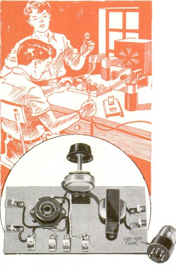
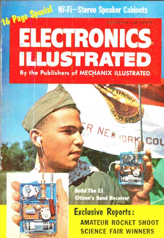
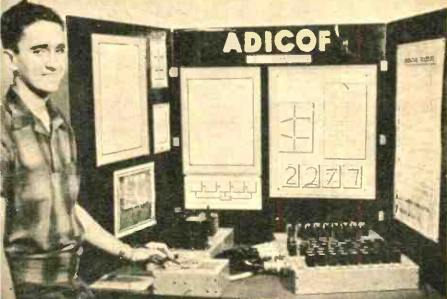
Shown here in the November 1960 issue of Electronics Illustrated is 17-year-old Belmont Frisbee, then a student at Burroughs High School in China Lake, California. He was one of the winners of the 1960 National Science Fair and is demonstrating his winning entry here. The device he constructed is dubbed “Adicof,” and allowed the entry of numbers into a computer by writing them by hand.

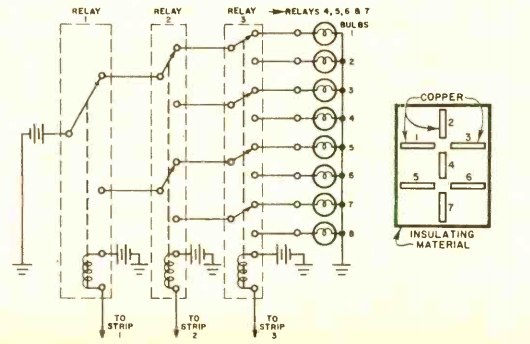
The digit is written with a metal stylus onto a panel with inlaid copper strips, as shown in the diagram below. For example, when making a “2”, the stylus will pass over strips 1, 2, 3, 4, 5, and 7.

The nearly forgotten art of relay logic is used to determine which number was being written. A partial diagram is shown below. Each strip is attached to the coil of a relay. The first relay is single pole, double throw (SPDT). The next one is DPDT. The one after that is 4PDT. Unfortunately, there probably weren’t any 128PDT relays on the shelf for the seventh relay, so multiple relays were used for the higher stages.

I believe the circuit shown here is simplified in one respect: For this to work, it would be necessary to use some type of latching relay, since the stylus would no longer be in contact with the pad when the next pad is contacted.

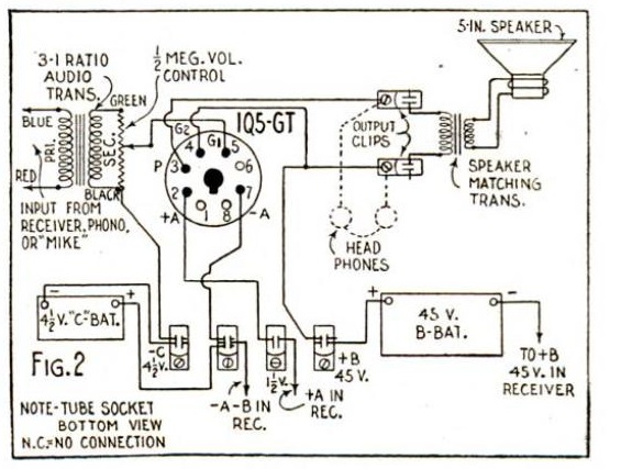
The simplified diagram shown here uses light to indicate the digit drawn, but for his exhibit, Mr. Frisbee hooked the output to a computer.

Today, it’s a trivial matter for a computer to recognize hand input, but the concept is nothing new. Sixty years ago, a high school student accomplished the task with electromechanical relays.

Mr. Frisbee continued as an engineer after high school. He was issued at least two patents (4,477,812 and 8,009,084), both of which involve radar, and both of which list the U.S. Navy as the assignee.

The magazine highlighted some other winners of the 1960 National Science Fair. Remarkably, it includes an electron microscope constructed by Marvin Hutt, a New York high school student, despite having experts tell him that making one at home was impossible. For students looking for inspiration for a science fair project, perhaps there are a few who could build an electron microscope from scratch. But in an age when computing power is taken for granted, there’s something to be said for being able to use mechanical relays for programmable logic. The science teacher might not even realize that it’s possible, and proving the impossible is always a good way to take home the blue ribbon.

1960NovEE4


1960 One Transistor CB Receiver

1960NovEISixty years ago, this New York scout made the front cover of the November 1960 issue of Electronics Illustrated by demonstrating this one-transistor superregenerative receiver for the 11 meter Citizen’s Band.

According to the accompanying article, a pair of CB transceivers would set you back about $150. But for many uses, one-way communication was sufficient. The example shown on the cover was “the Boy Scout out on a hiking expedition who wants to tune in home camp.” In addition, the article suggested that a physician might carry a small receiver on a large hospital campus to be paged. Or a TV serviceman working on a roof antenna could hear instructions from the ground.

This simple circuit would satisfy all of those needs. According to the article, the set would provide clear reception up to three miles without fading.

1960NovEI2


1940 Motorola Bike Radio

1940NovPS4Eighty years ago, this cyclist was able to enjoy her favorite program no matter where she happened to be pedaling, thanks to this three tube set shown in the November 1940 issue of Popular Science.  The set had a loudspeaker that faced the rider, and included an antenna that attached to the tip of the front fender and curved back. A separate battery box, supplying 90 volts B+ and 1.5 volts for the filaments, clamped securely to the bicycle frame.

While not identified by the magazine, the set appears to be a Motorola model B-150, featuring a tube lineup of 1A7GT,3A8GT, and 1Q5GT. If the set looks familiar, it’s probably because we previously featured it in connection with an ad allowing boys to win a free example by selling subscriptions to Radio Guide magazine.

Since this cyclist clearly isn’t a boy, she presumably paid the retail price of $19.95.


1950 Hi-Fi Demonstration Console

1950NovRadioNewsEighty years ago, this intriguing room could be found at Allied Radio in Chicago. Here, the Hi-Fi enthusiast interested in the very best equipment could be given a demonstration showing exactly how different pieces of equipment would sound together. Around the room were various tuners, amplifiers, preamplifiers, cartridges, tape machines, and other devices. From the console, different elements could be switched into and out of the circuit, and the discerning listener would be able to pick out exactly the right combination that met their needs.

The photo appeared on the cover of Radio & Television News, November 1950, which also included an article going into the room’s technical details.


Armistice Day Blizzard: 80th Anniversary

Armistice Day Blizzard, Excelsior Blvd., West of Minneapolis.  Minn. Historical Society photo, NOAA.

Armistice Day Blizzard, Excelsior Blvd., West of Minneapolis. Minn. Historical Society photo, NOAA.

Wednesday, Veterans’ Day or Armistice Day, is the 102nd anniversary of the end of World War I. But in Minnesota and the Upper Midwest, it is remembered as the 80th anniversary of the Armistice Day Blizzard of 1940, which was responsible for taking 145 lives. Here are two previous posts about that blizzard:

Newton “Jack” Baker III, 1920

NewtonJackBaker1920Shown here is Newton D. “Jack” Baker, III, the son of U.S. Secretary of War Newton D. Baker.

The picture appeared a hundred years ago this month in the November 1920 issue of Radio News, which reported that he had studied radio telegraphy enthusiastically, and had mounted this portable set on his bicycle, on which he listened while riding around Washington. With just the frame of the bike as an antenna, he was able to pick up NAA Arlington.

1919XmasRadioIf Master Baker and his radio look familiar, that’s because we’ve seen both of them previously. He had been an exceedingly good boy during 1919, and Santa Claus brought the radio as a reward, as shown in this close-up from the picture we previously shared. This photograph is clearly the same boy, the same radio, and even the same headphones as the Christmas photo.

I don’t see any record of Baker having received an amateur license, but it appears that he was an enthusiastic listener in the earliest days of radio.