 Yesterday, we showed a regenerative preamplifier from 1968, designed by Hartland B. Smith, W8VVD, currently licensed as W8QX. We promised that we would bring you another article by this prolific writer which appeared ten years earlier, in the September 1958 issue of Radio Electronics.
Smith begins the 1958 article by pointing out that he had been a licensed ham for 18 years and had his share of exciting DX contacts, but that he could “honestly say that none of these gave me quite as much a thrill as when I first saw an indentifiable transmission directly from London on the screen of my own TV set.”
And as shown by these pictures, that’s exactly what he did. The winter of 1957-58 was at the peak of the greatest solar maximum in recorded history, meaning that the maximum usable frequency (MUF) was frequently going above 40 MHz. This opened the possibility of pulling in Transatlantic TV signals, which is exactly what Smith set out to do.
Receiving the audio of British and French television signals was a relatively simple matter. The London and Belfast stations were on 41.50 MHz, and Caen, France, was on 41.25 MHz. Armed with nothing more than a prewar FM receiver, he was easily able to hear the audio. (Indeed, it wasn’t uncommon for American hams to listen to British TV audio on their six meter receivers.)
But being able to watch the video posed a much greater challenge. European TV used both different frequencies and different standards from American TV, so an American TV could not be used without some modification. So Smith set out to make the modifications. He focused on trying to pull in the powerful London station, which transmitted on 45 MHz with 200 kilowatts. The French station’s video was on 52.4 MHz, which was likely to be above the MUF even if the audio were booming in.
The first relatively modest challenge was the frequency, which was lower than that tuned by American sets. This was accomplished with a simple converter consisting of a single 12AT7 tube. With an oscillator frequency of either 33 or 123 MHz, this would bring the British signal to American channel 5, which was unused in his area. The antenna consisted of a two-element beam in the attic for video, with a folded dipole for the audio receiver.

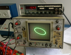
Lisajous pattern on scope showing equal frequencies. Wikipedia image.
Tuning in the signal was one thing, but getting a visible picture required that the set be modified internally. The first issue was the horizontal sweep frequency, which was 15,750 Hz in the American set, but 10,125 Hz on the British signal. He did this by using an audio oscillator to produce the required 10,125 Hz signal, and feeding this and the horizontal oscillator into a scope. He then adjusted the horizontal and added components until the frequencies matched, as shown by a circular lisajous pattern on the scope.
The British vertical frequency of 50 Hz was deemed close enough to the American 60 Hz to not require any modification.
The final problem was that the video carrier in Britain was opposite of that used in the U.S. To correct this, he modified the video detector by reversing the cathode and plate.
With the modifications made, it was just a matter of listening on 41 MHz and waiting for the audio of the European signals to appear. This meant that the band was open, and it was time to turn on the video receiver.
This was a fairly elaborate process. The first step was to turn on the converter, and adjust the converter frequency until the “familiar out-of-sync zig-zag lines denoting a video carrier” appeared on the screen. (Anyone who watched TV in the 1970’s or earlier knows exactly what he means. If you’re too young to remember, click here for an example.) At that point, the vertical hold would stop the picture from moving vertically, and then the horizontal hold control was adjusted (which might require some internal adjustment to make sure the control was in range). As he put it, “TV dx tuning is an art that is a little hard to describe on paper. It is best learned by experiment.”
He pointed out that picture quality would never be perfect. For one thing, there would almost always be multipath interference, since signals through the ionosphere might travel numerous paths. He noted that the ghosting problem might sometimes be acute. During one televised tennis match, he reported seeing at least 30 players batting 15 balls back and forth. But occasionally, the ionosphere would settle down momentarily, resulting in the identifiable images shown here.
