Category Archives: Radio history

1937 Two Tube Regen

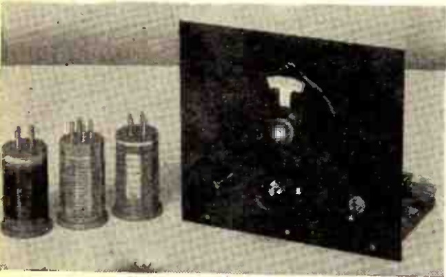
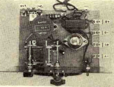
1937FebPS02Eighty five years ago, the February 1937 issue of Popular Science carried the plans for this two-tube regenerative receiver for the broadcast band up to 65 meters (about 4.6 MHz) with two plug-in coils. The set used two type 49 tubes, with the first one reflexed to serve as both RF and AF amplifier. The second tube served as regenerative detector.

The remarkable part of this receiver was that the B+ was only 11 volts. It used two dry cells for the filaments, which were also hooked in series with a 7.5 volt battery. The magazine noted that this made the receiver ideal for portable use, since the batteries were small enough to be carried in a pocket.

1937FebPS03


1942 Three Valve Emergency Receiver

1942FebPracWirelessEighty years ago, the January and February 1942 issues of the British magazine Practical Wireless showed the construction details for this three tube emergency receiver. The magazine had received many demands for a receiver capable of good performance on the medium waves, but with components that could be obtained with a minimum of difficulty, given the wartime conditions. The editors settled on this three tube design, with one tuned RF stage, which was found to perform adequately, but “shorn of refinements which would normally have been incorporated in times when components were easily and quickly obtainable.”

The main design was published in the January issue, with the February issue showing some refinements that would make the set more sensitive and selective. The February issue also showed how a two-tube version could be made, which might be necessary due to wartime parts shortages.

The regeneration control on this set is interesting, and something I haven’t seen before. It is a variable differential capacitor, which has two separate stators, and one rotor. The idea is evident from the diagram symbol. They are also sometimes called a split stator variable capacitor, and they apparently are a thing.

1942FebPracWireless2


1957 Two-Tube VHF Superregen

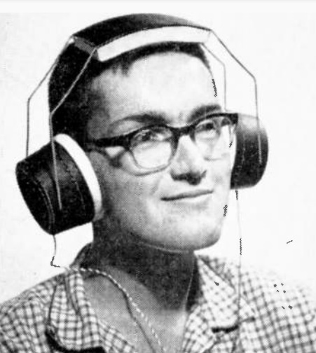
1957FebPE31This young man is exploring the action bands of the VHF spectrum with a two-tube superregenerative receiver from the February 1957 issue of Popular Electronics.

The set tuned 28-175 MHz, which included the FM and TV bands, as well as amateurs, police, fire, and aircraft. The magazine noted that the layout of the circuit was critical, and cautioned builders to construct it according to the photographs, in addition to the schematic. In particular, short lead lengths in the RF stage were critical.

A 12AT7 served as RF amplifier and detector, with a 6AF4 serving as audio amplifier. A signal generator was suggested for final calibration, but in the absence of one, TV and FM broadcast stations could be used to figure out the dial positions. Three plug-in coils were used for band switching.

1957FebPE32


1922 Boys’ Life Receiver

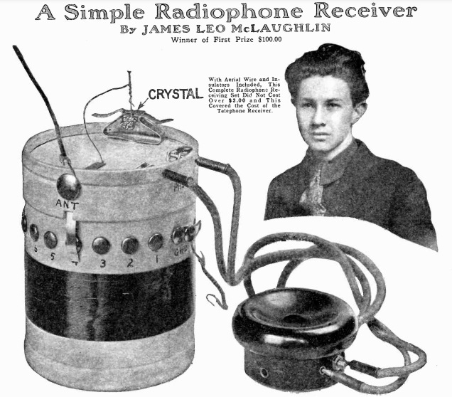
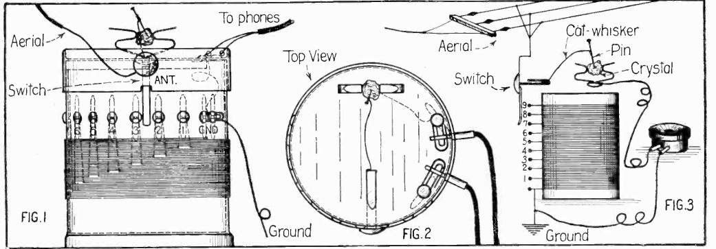
1922FebBLA hundred years ago this month, wireless column of the February 1922 issue of Boys’ Life showed scouts how to put together the simple radio receiver shown here.  The magazine noted that just a few years prior, there was still little to hear on the airwaves in most of the country.  Near the coast, it would be possible to pick up Morse transmissions to and from ships, and in larger cities, there might be a few signals here and there.

But in most of the country, there had been little to listen to.  But that ways changing, and by 1922, just about anywhere in the country, there were plenty of interesting signals just waiting to be pulled in.  In fact, even in areas without newspapers, the radio could be used to pull in stories straight off the news services, and it was possible to get sports scores long before your neighbors could.  There were even concerts being listened to by hundreds of thousands of people in many states.


TV Relay Tower, 1952

1952FebRadioElecI remember as a kid seeing a structure similar to this one. I don’t remember exactly where, but it was somewhere along the route between Minneapolis and Duluth, with one horn facing south, and the other facing north. I asked my parents what it was, and they said it was for relaying TV signals. It made perfect sense to me, since the two horns looked a lot like TV screens.

I didn’t know what was inside, but now I do. The electronics were on the top floor, the B+ power supply was on the third floor, the filament power supply was on the second floor, and a backup generator was on the ground floor.

This diagram appeared 70 years ago this month in the February 1952 issue of Radio-Electronics.  Click on the image to see the full size version.


1962 Phone Answering Machine

1962FebPSTelephone answering machines didn’t really become a thing until the 1970s, and even then, they were expensive and rare. At first, even their legality was dubious, since The Phone Company was jealous of anyone making any kind of direct electrical connection to the Public Switched Telephone Network.  I didn’t have an answering machine myself until well into the 1980s. Surprisingly, there was a time when the phone just kept ringing when nobody was home, and there was no way to leave a message. Similarly, if your phone rang, the only way to find out who was calling was to pick up the phone and talk to them.

For those who were unwilling to wait for the future, the February 1962 issue of Popular Science showed you how to put together your own answering machine. And since there was no direct connection to the phone line, you didn’t have to worry about provoking the ire of The Phone Company. When the phone rang, an inductive coil placed under the phone would sense it, and it would trigger a solenoid which would physically lift the button on the phone. It would also turn on the tape recorder, which had been left in the “play” position. The tape recorder would then play your outgoing message through the speaker, which was close to the telephone handset. At the end of the outgoing message on the tape, you had painted silver paint on the back of the tape. When this passed through an outboard sensor you had added to the recorder, it would trip a second solenoid, which would flip the switch on the tape recorder from “play” to “record”. The microphone was placed next to the receiver, and it would record for thirty seconds. At the end of this thirty-second piece of tape, there was another section of silver paint, which would reset the whole contraption for the next call.

You would need to prepare the tape in advance for as many calls as you expected to get, including multiple outgoing messages and silver paint sections.

For the outgoing message, you were instructed to tell the caller to leave their 30 second message when they heard the “click.” Presumably, the sound of the tape recorder switching over from playback to record would be sufficiently loud to serve as the cue.

To hear your messages, you would first glance at the tape to see if it had been used. If so, you would need to first remove the tape from the external switch, since running the tape through it unnecessarily would quickly remove the silver paint. You would then plug the tape recorder directly into the wall, rewind, and listen to the tape, which would include both your outgoing messages and the incoming messages.

As you can see from the schematic below, the control circuit used tubes, to switch the relays and solenoids. Since one of the relays was used to turn the tape recorder on and off, the tape recorder itself would need to be a solid state model, since there would not be time for the tubes to warm up.

After it was built, the device had to be adjusted. In particular, there was a sensitivity control for the circuit triggered by the ringer. In order to adjust it, the phone had to be ringing. And, of course, the only way to do that was to call someone else and ask them to call you.

1962FebPS2


1957 SWL’ing

1957FebPESixty-five years ago, people still dressed up to listen to the radio, as shown by this avid SWL shown on the cover of Popular Electronics for February 1957.

The magazine issue featured the shortwave hobby, and contained a number of pointers for pulling in foreign stations. The listener shown on the cover was well equipped, since she is shown with what appears to be a Hammarlund HQ-180, an excellent receiver even by today’s standards.


1962 Fallout Shelter Antenna

1962FebPMSixty years ago this month, the February 1962 issue of Popular Mechanics carried this hint for using an outdoor antenna in the fallout shelter. The magazine noted that the shielding required for fallout protection could also shield against vital radio broadcasts. Since most radios didn’t have an external antenna jack, the magazine showed how to add one. A small coil was placed over the loopstick antenna, and that coil was hooked to an outdoor antenna. For optimal reception, you would tune in a station close to 640 or 1240, the CONELRAD frequencies, and slide the coil along until the signal was strongest. At that point, you would add a little cement to fix the coil in place.

The antenna could be unplugged when in normal use, but quickly put to work in the shelter in time of emergency.


1952 One-Tube ARRL Handbook Receiver

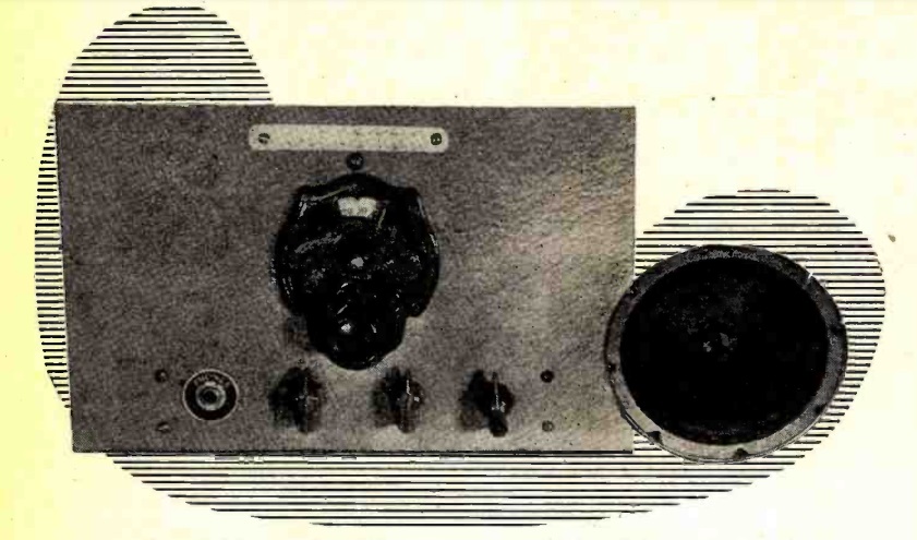
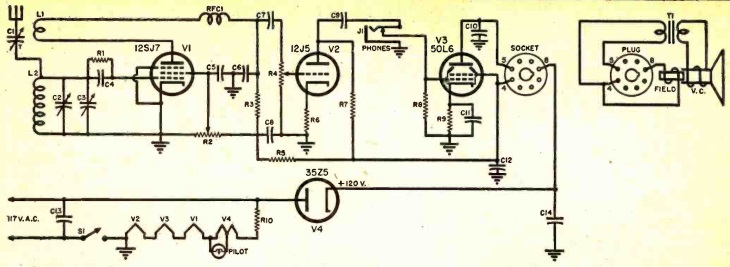
1952HB1Seventy years ago, the 1952 edition of the ARRL Handbook carried the plans for this handsome one-tube regenerative receiver. The set used a single 6SN7 dual triode, half of which served as detector, with the other half serving as audio amplifier. According to the book, the set was close to the minimum for a useful shortwave receiver, but under suitable conditions, it would pull in signals from many foreign countries. It was described as being excellent for the beginner, due to ease of construction and low cost.

With four plug-in coils, the receiver would tune 2.8 through 40 MHz, covering six ham bands, including the 11 meter band. Interestingly, the then-new 21 MHz band was called the “14 meter” band at the time. At some point soon thereafter, the name 15 meters was adopted, probably to avoid confusion with the 14 MHz band.

An accompanying power supply was also shown, built on a wooden-slat chassis.

1952HB2


1942: Modifying Enemy Alien Shortwave Sets

1942FebRadioServDealerAs we previously reported, as of January 5, 1942, enemy aliens (that is, citizens of Japan, Germany, or Italy) were prohibited from possessing cameras, firearms, or shortwave radios. They were required to surrender them at the police station, where they would be issued a receipt.

The February 1942 issue of Radio Service Dealer reminded its readers that the majority of such aliens were friendly to the country and should be accorded fair treatment. It was essential to keep in mind, however, that not all of them were. The magazine also pointed out that there was no intent to deprive enemy aliens of the opportunity of listening to American broadcast stations. Therefore, the regulations permitted persons to reclaim their receivers if it was made inoperative on the shortwave bands. Hence, there was a demand for technicians to perform the necessary task of disabling shortwave reception on multi-band sets.

The magazine stressed the need of doing so in a manner that could not be easily converted back. Therefore, simple modifications such as cutting a lead to a band switch, or shorting out oscillator coils, was insufficient. The magazine provided the technical details for various kinds of sets. Some sets, for example, used a single oscillator coil for both broadcast and shortwave, with the coil tapped for shortwave reception. These sets might require replacement of the oscillator coil. Other sets used separate coils for the different bands, and these were generally an easier job of simply removing the shortwave coils.

After the job was done, there was still a need for caution:

Remember that there is always the possibility that some enemy alien in your locality may try to pull a fast one. Dealers, jobbers and servicemen, and radio amateurs, too, should be suspicious of any person who may be presumed to be an enemy alien, when attempts to purchase radio parts, borrow test equipment, or seek your service in any alignment work outside of  the broadcast band.

On the other hand don’t let your imagination get the better of you. Be reasonably sure of your suspicions before reporting any case to the local police or the FBI.

The magazine contained the full text of the regulations:

Short-Wave Radio Receiving Sets

(a) No alien enemy shall use, or operate or possess, or have under his custody or control at any time or place any short-wave radio receiving set. For this purpose the words ‘short-wave radio receiving set’ are to be construed as including any apparatus designed to be used or capable of being used for the purpose of receiving signals, messages or communications of any nature whatsoever which signals, messages or communications are transmitted by means of radio waves of a frequency of 1750 kilocycles or greater, or of a frequency of 540 kilocycles or less.

(b) A short-wave radio receiving set as defined in paragraph (a) hereof which set is also capable of receiving long-wave radio communications is deemed to be within the class of shortwave radio receiving sets prohibited unless the set is so altered or modified that short-wave radio communications or messages cannot be received by the said set, and further, unless the set is so altered or modified that it is impossible without the addition of more parts and the substantial rebuilding of the set to modify the set so that it will be capable of receiving short-wave radio communications.

( c) No alien enemy who is found in possession of any short-wave radio receiving set will be excused in any manner on the ground that he did not know that the set was a short-wave radio receiving set or that the set could be readily converted into a short-wave radio receiving set. It shall be the duty of any alien enemy to ascertain whether or not any radio in his possession is prohibited; and any alien enemy having in his possession any radio receiving set whatsoever shall be held responsible for knowing whether or not such set is a short-wave radio receiving set.

1942FebRadioServDealer2The magazine apparently needed an appropriate photo for the cover to illustrate this important story, and it settled on this image of an SWL, apparently pulling in an English station. The caption noted that this activity was one now reserved to citizens only.

It’s not uncommon for radio collectors to come upon a prewar set whose shortwave bands have been disabled. For those with such a set, we hope this article provides some insight into the modification that had been made in early 1942.