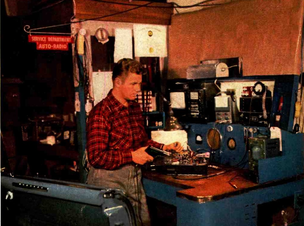
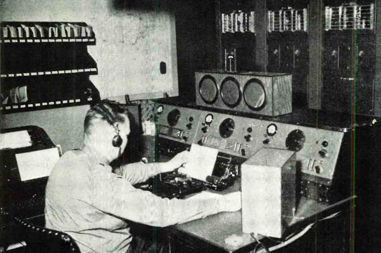
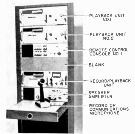
 Shown here, in the May 1972 issue of Popular Electronics is the console of one of NOAA’s weather radio stations. The operator could record a series of messages, which would repeat in a continuous loop. Another rack was at the transmitter location, and the two units were linked by telephone line.
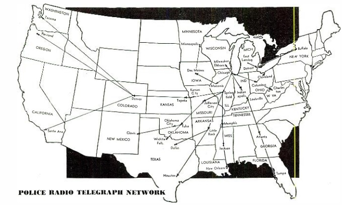
The Weather Service had started broadcasting on VHF-FM in the early 1950s, when the first transmitter was installed in Chicago. By 1972, sixty stations, listed at right (click image for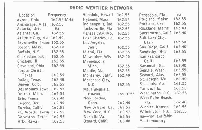 full-size version), were in operation throughout the United States. In the fifty ensuing years, the network has expanded even further, with hundreds of transmitters blanketing virtually the entire country. Starting in 1976, Environment Canada started a similar network, Weatheradio Canada, which now transmits from 230 sites across Canada. Mexico also has a similar service, SARMEX, operating on the same frequencies. The system broadcasts continuous weather forecasts, and alerts for watches and warnings.
A full coverage map is available on the NOAA website, but in most cases, it’s best to simply turn on the radio and see which station comes in strongest in your locality.
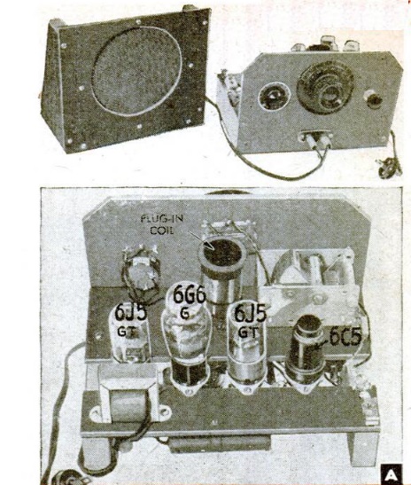
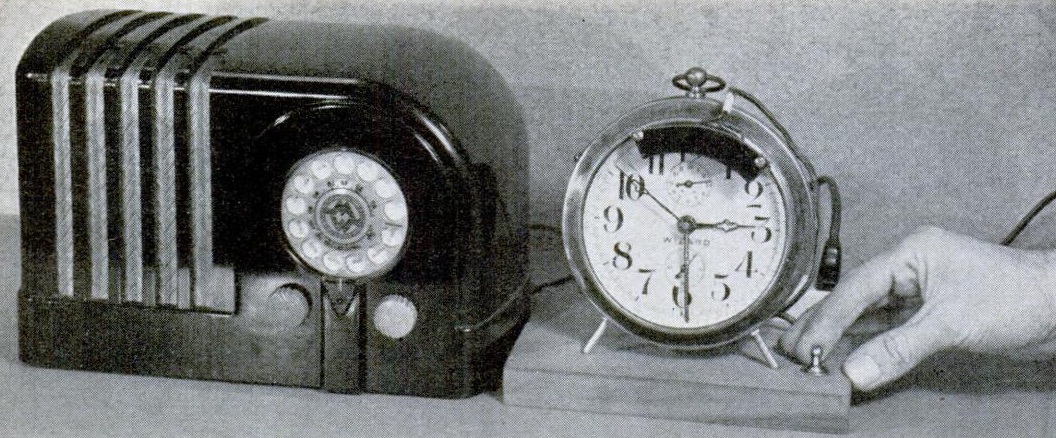
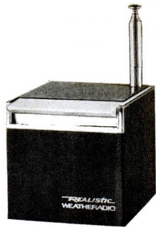 In 1972, the magazine noted that three types of receivers were available. Inexpensive receivers sold for $17 or less. One very popular entry in this category was the Radio Shack Weatheradio cube shown at left. The volume and analog tuning dials were on the bottom, so to hear the weather, you would simply push the bar on the top. More sensitive receivers started at about $70, and tone-alert models ranged from $150 to $300. Then, as now, weather watches and warnings were preceded by a 1050 Hz tone. A tone-alert receiver would be left on standby, and when an alert came through, an alarm would sound and/or the radio would turn itself on. The magazine noted that the expensive tone-alert receivers were in use by entities such as police departments and schools. But the price is now so low that there’s really no reason why Americans should not own one to receive alerts about weather and other emergencies.
NOAA now precedes warnings with Specific Area Message Encoding (SAME), which is a digital squelch which turns on the receiver for specific types of warnings for specific areas. If the weather radio station covers a large geographic area, this allows the user to set the receiver for, for example, only warnings affecting a certain county or counties.
In 1972, the inexpensive $17 receivers were invariably not very sensitive. They would typically work well close to the transmitter location, but didn’t have sufficient range for outlying areas. Typically, they had analog tuning, using circuitry similar to a normal FM radio. The more expensive units (starting at $70) were typically crystal-controlled, with a switch to select the receive channel. They were typically much more sensitive and could be used in fringe areas.
Today, even the most inexpensive receivers usually have digital tuning, and have very good sensitivity. Almost everyone in the United States can now receive a weather station with even an inexpensive receiver.
Many of the inexpensive radios can be kept silent monitoring for a tone alert. Receivers with SAME technology, which can be programmed for a specific area, are also now surprisingly inexpensive.
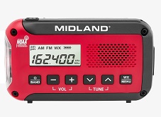 My personal favorite is the Midland receiver shown here. In addition to being an excellent receiver for the weather band, it also tunes normal AM and FM broadcasts. It does have the standby feature which allows it to listen and sound the alarm in case of an alert. It includes a flashlight. It uses 3 AA batteries.
An even better option is the similar model that requires no batteries. It contains a rechargeable battery, which I normally keep charged by connecting it to a normal cell phone charger after several days of use. But if I ever forget, it includes a hand crank and solar panel, meaning that it can be used indefinitely without any power source. It can also be used to charge a phone or other USB device.
An even cheaper option is a simple radio like this one. It doesn’t have the alert feature, but you can turn it on when the weather looks bad. It also includes a normal AM-FM radio, an runs on AA batteries. Because it has a tuning dial, it’s not quite as sensitive as digital receivers, but in most areas (especially metropolitan areas), it will pull in the local station.
 If you are looking for a weather radio to use 24/7 to monitor for alerts, then I recommend this model or a similar one. It has a very sensitive receiver, and will work almost anywhere in the United States. More importantly, they operate off AC power, so you don’t need to worry about changing batteries, as you’ll leave it turned on standby 24/7. But they have battery backup, and switches to batteries automatically if the power goes out, which can often happen during weather emergencies. It has SAME technology, which allows you to program it to sound the alarm only for certain counties. For information about how this model is especially useful for persons who are deaf, please see our post on Weather Radios for the Deaf.
For activities such as camping, where a set of walkie-talkies might come in handy, you should consider a radio such as this one. It combines an FRS/GMRS radio with a NOAA weather radio, complete with alert.
One hint for those who are outdoorsmen or travel for any reason, it’s always a good idea to know what county you are in. Watches and warnings are usually given by county, and without this information, you might miss an important warning. This website will tell you what county you are in, but it’s a good idea to find this information before an emergency, in case your internet becomes unavailable.
Some might say that a weather radio is less important than it was 50 years ago. After all, you have a cell phone that provides instant weather information. However, that cell phone is dependent upon your local cellular network and/or WiFi. A power outage in your area could mean that you are suddenly without any means of notification for severe weather. A weather radio is a cheap investment to make sure you have constant access to emergency information.
Some links on this site are affiliate links, meaning that this site earns a small commission if you make a purchase after clicking on the link.