Category Archives: Radio history

Transformer Science Project


1946FebBL75 years ago, this young man discovered the secret for meeting girls. That, of course, was explaining to them how transformers worked. This young woman is obviously mesmerized by his explanation.

He gained this skill by conducting the experiment shown below. He constructed his own transformer with two coils of wire wound around an iron core. To provide the alternating current, he runs one wire along the file.

1946FebBL2

These items appeared as part of an for Westinghouse in the February, 1946, issue of Boys’ Life.  It reminded readers to tune in to programs sponsored by the company, John Charles Thomas and Ted Malone.

The science project is easily duplicated today.  While the old-style dry cell battery is no longer available, an alkaline D cell, with suitable holder, would work just fine.  The other items needed are wire, the bulb (with socket to make the connections easier), an iron bar, and file.


1941 Breadboard Crystal Set

1941JanPM3The plans for this crystal set appeared 80 years ago this month in the January 1941 issue of Popular Mechanics. Laying out a circuit in this manner is often called “breadboarding,” and this picture shows why.  The chassis for the set was a literal breadboard.

In addition to serving as a radio, the set could also be used as a piece of test equipment.  It had terminals for incoming AF or RF, and could be used as a signal tracer to troubleshoot other radios.


1941JanPM4

Detroit Radio Concerts, 1921

1921JanTalkMachWorld2This photo, in the January 1921 issue of Talking Machine World, shows an early radio broadcast taking place a century ago in Detroit.

The magazine noted that a number of well-to-do residents and members of the Detroit Radio Association were able to tune in radio concerts and dances, furnished by the Edison phonograph, “providing diversion simultaneously in a number of homes, of which some actually are located between four and five miles away.” In some cases, musicians played in unison with the phonograph.

Among the younger set, radio dances had taken a permanent place as a popular pastime, “in the home of those fortunate enough to have had the necessary receiving apparatus installed.”


1961 BSA Radio Gear

1961JanBLSixty years ago, the Boy Scout with an interest in radio could get everything he needed to get started from the BSA National Supply Division at his local official BSA dealer, as shown here in the January 1961 issue of Boys’ Life.

He would very likely be the first on his block to own a transistor radio by putting together one of three kits. The simplest one, which probably required an outdoor antenna, was a fixed diode plus one transistor, which would set him back $4.50. The two transistor model would pull in more stations for $8.95. And everyone would be impressed if he put together the $14.95 three-transistor set, which would give loudspeaker volume.

The beginner could put together the crystal set for only $2.96, complete with cardboard base. And to pull in the shortwaves, the tube set for $15.95 wouild get both broadcast and shortwave.

For code practice, there was a signal set for $1.95 each or $3.95 for two. If the Scout was good at math, he would realize he was paying a nickel more if he bought two, but that’s explained by the fact that it came with 30 feet of wire. And to get started, a code record could be had for $2.95.


1921 Printing Radiotelegraph

1921JanPScodereaderThis gentleman, shown in the January, 1921, issue of Popular Science, wasn’t a QRQ operator, but he was still able to copy even the fastest radiotelegraph stations thanks to this device developed by William G. Finch of Buffalo, New York.  Instead of the familiar buzz in the headphones, the code was rendered as dots and dashes printed on paper tape, which could be read at the operator’s leisure.  The device employed an ultra-sensitive relay along with an “ordinary printing telegraph machine.”

The “ordinary printing telegraph machine” had actually been around for quite some time, since the first telegraphs were designed to print the dots and dashes, rather than be copied aurally.  It was later discovered that the operators could hear the letters as they came in, and that became the norm.


Ernest Sperling, 9BBF, W9BKX

1921Jan26NewUlmThis article appeared a hundred years ago today, in the January 26, 1921 issue of the New Ulm (MN) Review.

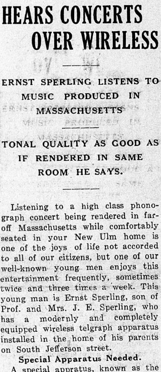
HEARS CONCERTS OVER WIRELESS

ERNST SPERLING LISTENS TO MUSIC PRODUCED IN MASSACHUSSETS

TONAL QUALITY AS GOOD AS IF RENDERED IN SAME ROOM HE SAYS

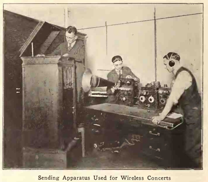
Listening to a high class phonograph concert being rendered in far off Massachusetts while comfortably seated your New Ulm home is one of the joys of life not accorded to all of our citizens, but one of our well-known young men enjoys this entertainment frequently, sometimes twice and three times a week. This young man is Ernst Sperling, son of Prof. and Mrs. J. E. Sperling, who has a modernly a completely equipped wireless telegraph apparatus installed the home of his parents on [21] South Jefferson street.

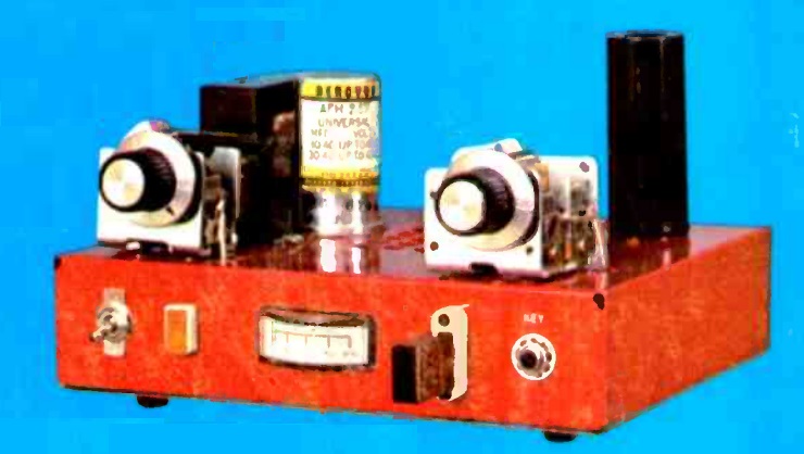
Special Apparatus Needed.

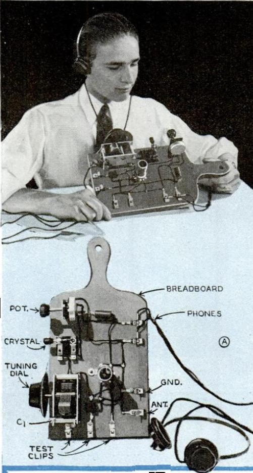
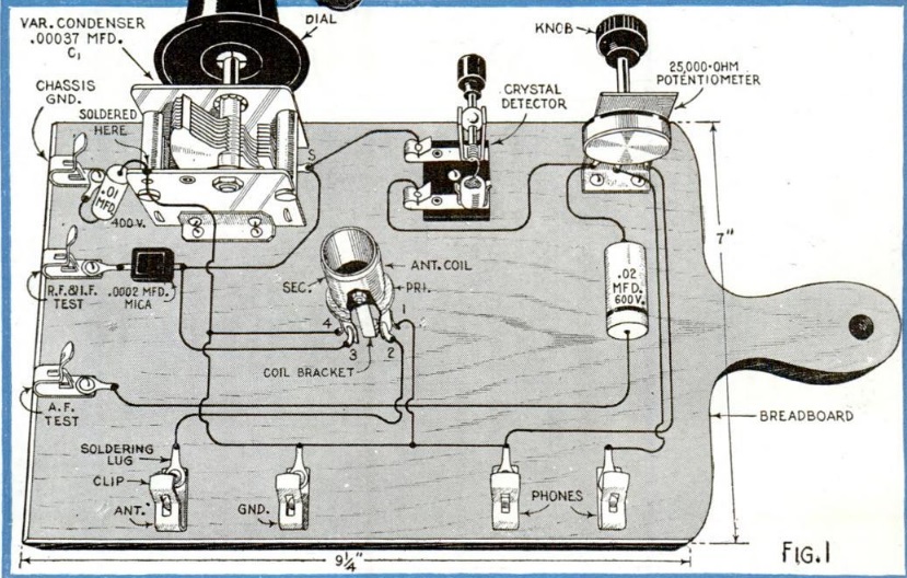
A special apparatus, known as the audion receiving set, is necessary to receive music by wireless. This apparatus is more sensitive and of a better grade than the regular wireless receiving instrument. There is very little electrical energy used in transmitting music waves by wireless, so that the detector must be unusually sensitive, or the other tones will not be clear. Another important factor in the transmission of music via wireless is the prevailing weather conditions. If the air is clear and quiet, with no perceptible wind, the music is much more audible and there is no rising or falling of the tone During a wind that is strong enough to sway the antenna the music sounds as if it were being played on a phonograph, the modultor of which is being changed constantly.

News Every Night.

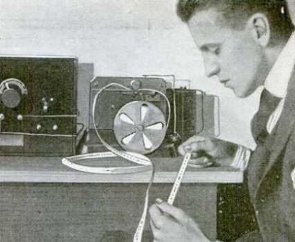
Mr. Sperling spends a considerable part of his spare time evenings at his wireless instrument and receives many messages containing accounts of important happenings not only in this country but abroad also. One of the principal sources of this in formation is the big wireless station on Arlington Heights, near Washington, D. C., from which such messages are sent out every evening. He also receives messages from commercial stations every section of the United States, the most distant one being located in Alaska.

“Connect” With Europe.

Mr Sperling is at present working on a large receiving set, which, when completed, will enable him to get wireless messages direct from Europe, thus enlarging the scope of his wire less work. Quite a number of interested New Ulmites have visited the Sperling home to view the young man’s wireless apparatus and have him explain its workings.

Later in the year, the newspaper’s June 1, 1921, edition reported that young Mr. Sperling had agreed to supply farm market reports to the telephone company, which made them available to local farmers.

Sperling is listed in the 1922 callbook as being licensed as 9BBF (with his name spelled Ernest). His father, Prof. J.E. Sperling of Dr. Martin Luther College is listed in this yearbook as a Pastor Emeritus of the Joint Wisconsin Synod of the Lutheran Church.

In the 1937 callbook, Ernest is listed as one of two licensees, along with one Victor H. Schleuder, as licensee of W9BKX of 313 S. State St., New Ulm. He is listed in the 1940 census as living at 21 South Franklin.
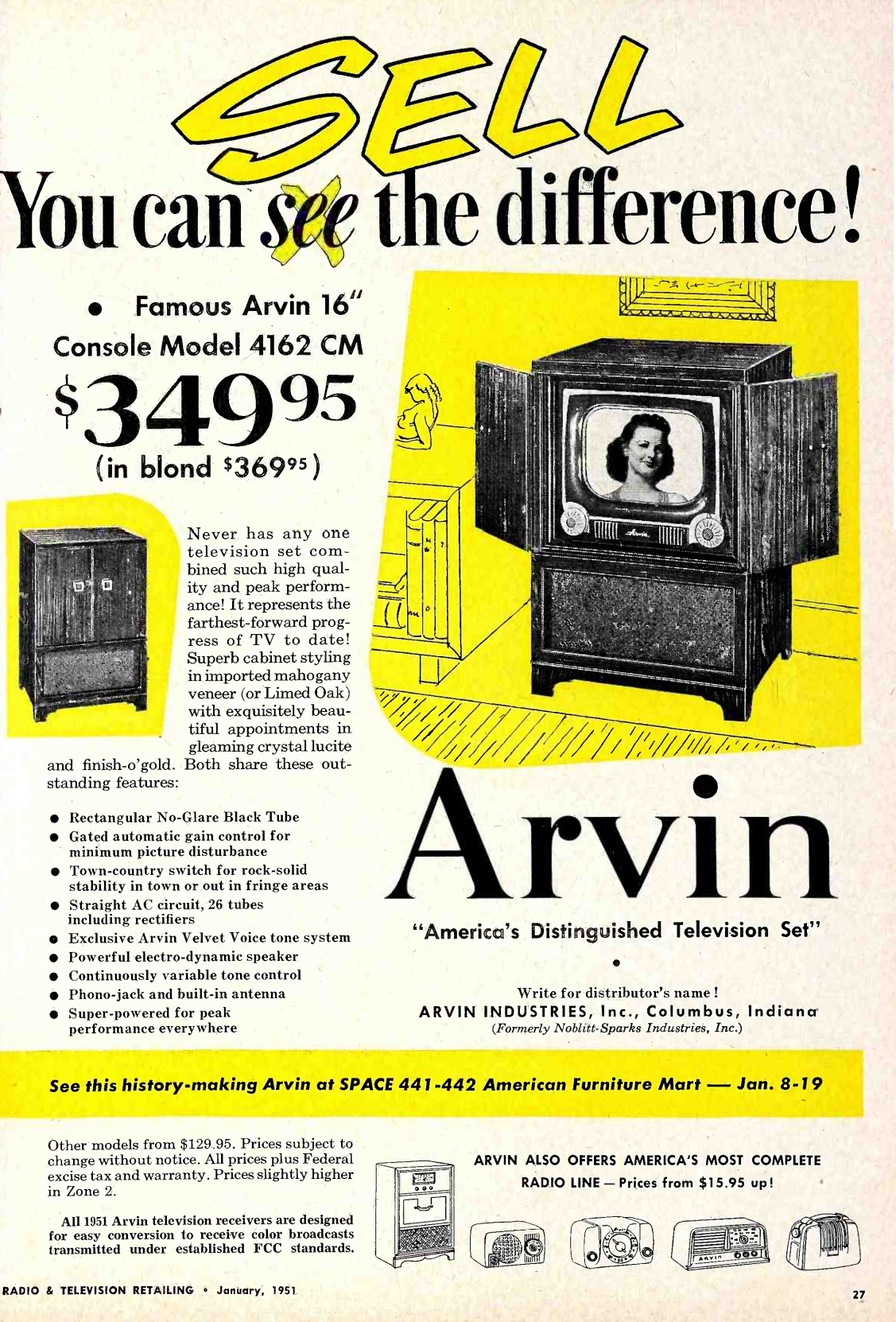
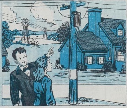


Print Your Own Postcards: 1951

1941JanRadioRetailingA80 years ago, the small retailer, such as a radio dealer, would probably find this to be a very economical way to advertise. For $8.50, he would get everything necessary to print postcards himself, and then he could mail them out for one cent.

The device is a small mimeograph, or stencil duplicator.  The mimeograph should not be confused with the spirit duplicator, or ditto machine, although it often is.  The mimeograph used a stencil, a thin membrane which was physically cut by a typewriter without a ribbon.  The ink was forced through the resulting holes, making a very good image.

This inexpensive model was smaller than most, but could print a postcard in much the same way that one would use a rubber stamp.

If you’re looking for another antique method of printing, check out my hectograph page.

The ad appeared 70 years ago this month in Radio Retailing magazine, January 1951


1951 Arvin Model 4162 CM Console TV

1951JanRadioTVRetailingThis ad for Arvin Television appeared seventy years ago this month in the January 1951 issue of Radio & Television Retailing.

It highlights their top-of-the-line console, the 16 inch model 4162 CM, which retailed for $349.95 (or an extra $20 for a blond cabinet), plus federal excise tax and warranty. Other sets started at $129.95, and the ad reminded dealers that the company had America’s most complete radio line, starting at $15.95, all of which rolled off the assembly line of Arvin Industries, Inc., of Columbus, Indiana.


1946 Radio Listings

1946Jan23WashEveStarIf you had tuned in on the radio in Washington 75 years ago today, January 23, 1946, here is what you would have heard, according to that evening’s edition of the Washington Evening Star.


1971 Two Transistor Transmitter

1971JanEIFifty years ago this month, the January 1971 issue of Electronics Illustrated carried the plans for this transistorized CW transmitter for 40 and 80 meters. The magazine noted that even though transistors had caught on for many electronic applications, tubes were still the most common for transmitters, due not only to the high cost of RF transistors, but also due to output impedance matching problems.

The design solved these problems by using high voltage transistors originally intended for audio amplifiers running off 117 volts. These allowed high impedance matching with the pi-net antenna tuner that hams were accustomed to.

The transmitter used two RCA 40321 transistors, which still seem to be available as New Old Stock (NOS) items. They were run in parallel as a Colpits oscillator. The heat sinks of the small transistors were mounted to a piece of aluminum mounted below the main chassis, which had holes drilled to allow the transistors to cool.  The transmitter had an input power of 17 watts.

1971JanEI2